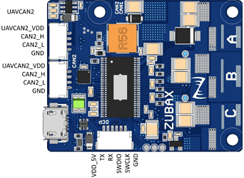
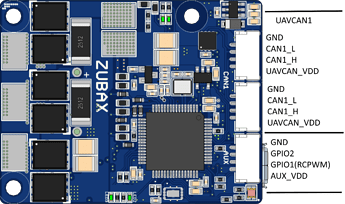
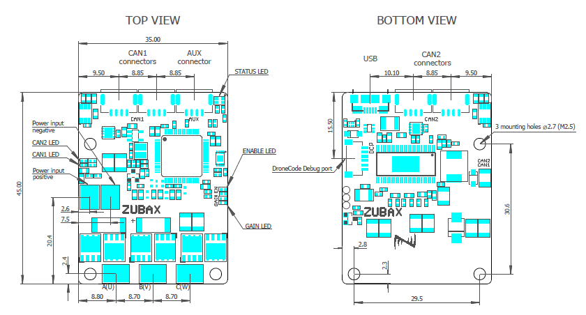
Integration instructions for Myxa are not yet written; however, we have them for Sapog, and seeing as Myxa’s communication interfaces are largely similar to those in Sapog, we suggest our early customers to refer to the following guides, keeping in mind the differences in configuration parameters, which we’re going to review here next: Sapog BLDC motor control solution - Knowledge Base - Zubax Knowledge Base.
Configuration parameters
In this section, we’re going to walk through some of the most important configuration parameters available in Myxa. Most configuration parameters take effect virtually immediately or at the next use, so in most cases, it is not necessary to restart Myxa.
Common abbreviations:
-
eangvel - electrical angular velocity; always in electrical radian/second.
-
ctl - control.
-
ttl - time-to-live - the amount of time between the last command received from the given interface until the motor is stopped automatically.
Motor control
Motor control parameters are contained in the section m; for example, m.max_current. Some of the parameters in this section are deduced by Myxa automatically if they are not provided by the user. It is, therefore, necessary to reset all of the parameters in the group if you’re switching Myxa to a different motor; otherwise, the auto-deduced parameters will keep their old values.
All parameters in this group take effect when the motor is started or re-started. Restarting the whole device is not necessary.
-
m.num_poles - the number of magnetic poles on the rotor; equals the number of magnets on the rotor; always an even number.
-
m.max_current - rated phase current of the motor, in amperes (more on this later).
-
m.min_current - minimum current at which sufficiently stable operation of the drive is guaranteed. Deduced automatically from the previous parameter; can be changed by the user if necessary. You should lower this value if your application requires low-speed operation.
-
m.flux_linkage - magnetic flux linkage in weber; measured automatically.
-
m.resistance - phase resistance in ohm; measured automatically.
-
m.induct_direct - direct axis phase inductance in henry; measured automatically.
-
m.induct_quad - quadrature axis phase inductance in henry; measured automatically.
-
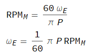
m.min_eangvel - minimum electrical angular velocity, in electrical radian/second, at which sufficiently stable operation of the drive is guaranteed. You should lower this value if your application requires low-speed operation.
-
m.max_eangvel - maximum rated electrical angular velocity, in electrical radian/second. Raise this value if the motor does not reach required speed levels in the RPM control mode.
-
m.current_ramp - the maximum rate of change of the quadrature current setpoint (Iq), in amperes per second.
-
m.voltage_ramp - the maximum rate of change of the quadrature voltage setpoint (Uq), in volts per second. Generally, values above 10 V/s require a higher setting of m.current_ctl_bw, otherwise the stability can be compromised.
-
m.eangvel_accel - the maximum permitted acceleration, in electrical radian per second per second. It is likely that this value will need to be increased for multirotor drives.
-
m.eangvel_decel - the maximum permitted deceleration, in electrical radian per second per second. It is likely that this value will need to be increased for multirotor drives. Do not exceed 10000 radian/second^2.
-
m.eangvel_ctl_kp - P gain of the RPM PID controller. Units: ampere*second/electrical_radian.
-
m.eangvel_ctl_ki - I gain of the RPM PID controller. Units: ampere/electrical_radian.
-
m.eangvel_ctl_kd - D gain of the RPM PID controller. Units: ampere*second^2/electrical_radian.
-
m.current_ctl_bw - the bandwidth multiplier of the current control loop; unitless. At very high ramp settings, especially in the voltage control mode, this parameter should be increased in steps of 0.02. Generally, values up to 0.1 are safe.
BEC
There is only one parameter in this group; it is valid only for Myxa B: bec.can_pwr_on. It defines whether the BEC (battery elimination circuit) power output is enabled or not. The parameters takes effect immediately.
UAVCAN
All parameters in this group take effect after a reboot.
-
uavcan.node_id - the UAVCAN node ID. If set to zero, which is the default, Myxa will attempt dynamic node ID allocation.
-
uavcan.esc_index - the index of this ESC on the vehicle. Set to zero by default; must be configured manually.
-
uavcan.esc_ttl - deadman switch timeout, in seconds.
-
uavcan.esc_rcm - RCM stands for “ratiometric control mode”. This setting defines which control mode to use when interpreting the message uavcan.equipment.esc.RawCommand:
- 0 - current control mode
- 1 - RPM control mode
- 2 - voltage control mode
Beware that Myxa does not support automated ESC index assignment. The parameter uavcan.esc_index must be configured manually.
RCPWM
All parameters in this group take effect when the RCPWM signal is connected, i.e. in order to apply new parameters, disconnect the RCPWM cable from the device and then connect it back at least 0.1 seconds later. An exception is rcpwm.enable - out of safety considerations, this parameter takes effect only after reboot.
The basics of RCPWM are explained in the relevant section of the Sapog reference manual, and some useful information is also provided on Wikipedia.
-
rcpwm.enable - whether to enable the RCPWM interface. Requires reboot.
-
rcpwm.pulse.bot - minimum duration of the RCPWM pulse, in seconds.
-
rcpwm.pulse.mid - duration of the RCPWM pulse that is treated as a zero setpoint, in seconds; i.e. the motor will be stopped.
-
rcpwm.pulse.top - the maximum duration of the RCPWM pulse, in seconds.
-
rcpwm.ttl - deadman switch timeout, in seconds.
-
rcpwm.ctl_mode - which control mode to use with RCPWM:
- 0 - current control mode
- 1 - RPM control mode
- 2 - voltage control mode (default)
By default, the range parameters are set up as follows:
-
rcpwm.pulse.bot - 1 ms
-
rcpwm.pulse.mid - 1.5 ms
-
rcpwm.pulse.top - 2 ms
Which implies that the motor will be stopped when the pulse is 1.5 ms long; run forward if the pulse is longer than that, and reversed if the pulse is shorter than that. In order to configure unidirectional operation, set rcpwm.pulse.mid to 1 ms.
