I think this bears some relevancy to the power balance explanation, and perhaps understanding of listed settings and any hard-coded limits.
I have been experimenting with a Myxa running Telega v0.2, to see how much power I could squeeze out of it, within the (peak) limits as I understood them. The particular unit is dedicated to the test bench, so I could afford some risk.
Whereas I am able to configure max_current (phase current) with values up to 60A, there appears to be a hard-coded limit of 30A on the derived DC link current.
As soon as the DC Current in the GUI reaches 30A (Phase current peaks around 42A), I receive a “DC Overcurrent” Alert, the system throttles down and begins to oscillate with a downward trend. I also start to see “CSSW Saturation” engaged and “Hardware Overload” messages. Is this DC Current limit configurable behavior, or a static safety-related limit? Or am I missing something else entirely given the messages?
If more information is needed, I have some screenshots (I don’t wish to unnecessarily clutter this topic).
Myxa does not apply any implicit setpoint constraints in the software. ESCs which do (e.g., any no-name) are flawed and are fundamentally unfit for use in flying vehicles.
Practically that means that once commanded to reach a particular setpoint, Myxa will attempt to do so regardless of its state (temperature, current limits, etc). An exception applies to the last-resort hardware protection against extreme overload which exists only to prevent the device from catching fire (as opposed to mildly overheating), which is exactly what you seem to be observing judging by the message “Hardware Overload”. The hardware overload protection is the very last line of defence which is activated independently of the control software directly by an analogue circuit in the power stage. Reaching this stage indicates that you are overloading the device dramatically (which does seem to be the case here: at 30Adc*50Vdc you would be approaching 1.5 kW of steady-state power output). Regarding the downward trend, it is difficult to say what exactly is happening in your case, but my educated guess is that once the hardware overload protection is activated, its limiting behavior interferes with the motor control logic, increasing the phase error, which in turn leads to an even higher power dissipation in the drive. The positive feedback causes the downward trend.
The solution is to avoid such high currents or to switch to a more powerful controller. Speaking of which, are you aware that we have OpenMyxa rated for up to ~2.5 kW and a new upcoming design Voguerode rated for up to 7 kW? They run the same firmware. If you’d like to learn more about those, please email my colleague dmitry.ramensky@zubax.com.
Thank you for moving this into its own topic - I wasn’t sure it was sufficiently novel, but now I can supply more information without cluttering the old thread.
At this point I can accept the standard Myxa falling short of supplying the necessary current, and I will contact your colleague regarding the OpenMyxa design. I have been reviewing the design these past couple days, as it seems to fit our power requirement perfectly - I mistakenly assumed that it was not yet ready for testing.
That said, in the interest of not sounding crazy (putting 1.5kW through a Myxa level of crazy), here’s some hardware information:
Battery: 6s (25.2V max) Lithium Ion pack
Motor: KDE4215XF-465
I’ve reviewed the video I recorded, and the peak phase current I witnessed was 47.4A (775W).
Do you know off hand what shunt current would trip the hardware overload? Perhaps the GUI sampling was missing the peaks.
I have read up on some of your other posts, and wonder if this excerpt may have bearing:
Considering the reported RPM and known Kv of the motor, that is.
It may be a rather inconvenient medium, but I have attached a screen recording of my testing. I apologize for the periods of inactivity, as the test stand was in a protected enclosure and slowed down the testing. DC Overcurrent is first reported at the 2:45 mark, and gets more interesting from there.
The overload protection is based on the voltage drop across the low-side bridge transistors, and as such, the threshold tends to float quite a bit. It is designed so that the lower boundary is to be above 40 A.
First, the hardware overload protection activates at around 40-50 A. The protection is very invasive; while active, it directly modifies the PWM signal pattern carefully constructed by the sophisticated control logic, which you can mentally picture as throwing a wrench into the motor control loop. The control logic perceives this as a very strong external disturbance and attempts to recover; while the recovery is in progress, the phase error oscillates wildly, randomly causing the protection to trip again, throwing the control loop back into square one. The process repeats some dozens of milliseconds later unless the demand is reduced.
I’m using the Myxa A2 with T-Motor MN5212 KV420 and I’m receiving the same issues as above.
I’m using a power supply set at 22.2V (which is the nominal for a 6s battery). Following the ‘phase voltage’ comment from you Pavel I increased the voltage to 30V but the outcome is still the same.
Even from a cool ESC (<40°C) I can’t get the motor (plus prop 18x6) to get past 32-34A. At 22.2V this is only around 710-755W which is not even close to rated power.
Any idea how to rectify this issue?
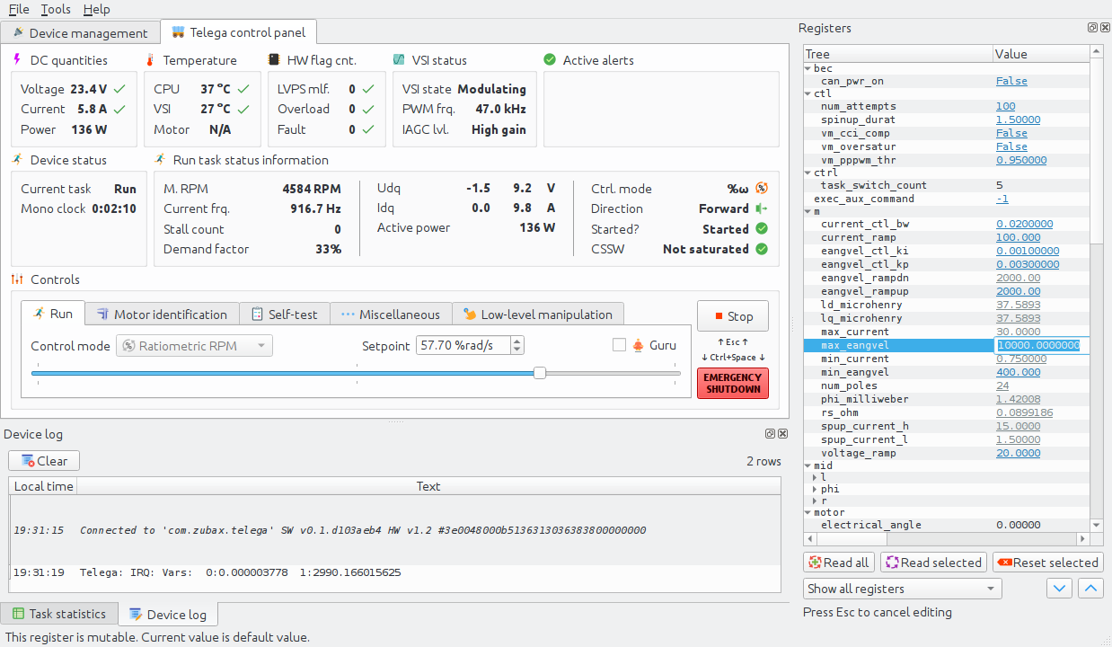
Can you tell us what is the value of the phase current? It is displayed in Kucher and published via UAVCAN v0 as uavcan.protocol.debug.KeyValue with key=iqf.
Sorry a bit new to this.
Where is the value displayed in Kucher?
Do you mean you want the phase current just before the errors come up i.e. when the motor is running?
When the motor is running, in section “Run task status information” there is a little table with Udq/Idq in it (rotating system current and voltage). We need the last value in the Idq row, which is the quadrature axis current. On this screenshot, Iq is 9.8 A:
Okay, I see – you are indeed tripping the hardware overload protection. As I wrote here earlier, the limit is set at 40-50 A, you are pushing it to 44 A.
We recently released Myxa v1.5 which looks the same but the overcurrent trip level is increased. If this condition creates a problem for your application, we can either replace your old Myxa with v1.5, or privately send you instructions explaining how to upgrade on the spot (it is a rather trivial modification). If you are interested, please, reach out to my colleague at dmitry.ramensky@zubax.com (he is aware of this thread already).
Thanks for the answer. Doing the v1.5 modification on the spot doesn’t sound like a problem to me but the thing is we need our motor/prop combo to be able to provide around 6.4kgf. I have managed to get this using the T-Motor Flame 80A HV at 30V and 63A (that’s on the power supply output) meaning we would need to reach around 1900W for a few seconds (maybe 5-10) during flight. Our batteries are 6s therefore we will draw closer to 85A on the ESC input side. If there is a way to get this (using the suggested or a more drastic mod) from the Myxa A2 let’s go for it, otherwise we will need to find an alternative ESC.
This is likely to be infeasible for Myxa. It should be possible to get it to work under these conditions but putting that into production is unsafe because it is out of spec.
The Komar sounds like the right solution moving forward but it will require some mechanical and electrical mods to the drone. Do you have stock ready to ship? If there is a way to get the Myxa A2 to operate close to 1500W safely so we can get the first flights under our belt until we get the ESC replacements that would be a good intermediate step - even if it means we ‘void’ the A2 warranty.
Looking forward to your suggestions.
Sure. No guarantees but the modification I mentioned might help here. Do contact Dmitry for that via email I left above, please. He is aware of your case.
Yes. If you’re in EEA, we can probably ship today.
I have now received the Komar and I have just started to test it on RCBenchmark. Managed to reach about 1040W before the ‘CSSW Saturation’ light comes on. Still running on 22.2V (for battery min voltage reasons) and have about 120A available on my power supply.
Here are my current settings. Any idea how to remove this limitation? As reminder the motor needs to reach approximately 1950W at max rpm (close to 7500).
CSSW means that you’ve exhausted the available voltage, so the controller is unable to increase the current further. There are three solutions:
Increase the supply voltage.
Use a different motor with a lower magnetic flux linkage (higher KV).
Enable field weakening.
The latter option allows you to get going without changing your hardware configuration but it is tricky to set up and is largely experimental. It also comes with some energy penalty since some of the power supplied to the motor will be used to suppress the magnetic flux of its permanent magnets.
At 22.2V and using the T-Motor Flame 80A I managed to get about 1250W of electrical power.
Even with field weakening enabled the Komar ‘saturates’ at 1040W…
More worryingly Kucher now freezes when I’m close to max throttle which means I can’t stop the motor unless I pull out the power cord!
Additionally, I enabled the pwm control to see if I can run through RCBenchmark and I get no response when I try to run it there. I have restarted Komar a few times.
Switching the field weakening flag is not enough to get it to work. I strongly advice you to return that option back to its default value to prevent damage to your hardware because keeping it on without proper tuning is highly dangerous.
Pulling the power cord is not necessary to stop the motor. If you are experiencing issues with software, disconnecting the interface cable (USB/UART) is an easier way to stop the motor.
USB is known to misbehave at high power levels especially if the cable is long and unshielded. Try using better/shorter cable, or use UART (it may not be directly accessible with your Komar though).