OK, will do.
OK, good to know.
Yes, it previously worked for Myxa A2 but not Komar
OK, will do.
OK, good to know.
Yes, it previously worked for Myxa A2 but not Komar
Please note that RCPWM interface won’t work if you have connected USB and run Kucher or if you enable the UAVCAN interface and send the setpoint via CAN.
I will try this today.
On this subject, how can I get the Komar to produce a higher power output? What other settings can I change? The phase current never went above 65A. This can’t be the limit of the ESC (even at 22.2V).
Please advise in which mode do you run Komar: RPM control or voltage control mode? In the RPM control mode, besides the battery voltage, the maximum electrical speed is limited by m.max_eangvel.
If I got you right, the Overload counter is not increasing in your case. It means that it’s not the hardware limit.
If all of the above is fulfilled, the next step to increase the motor speed is to set field weakening mode as it described in the post.
It is RPM control.
I have increased this to the max. of 20000 (I believe) but didn’t see much change.
Agreed.
I will look at this today and come back to you.
Another question:
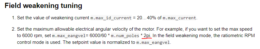
Here you have 2pi:
but here you show just pi.
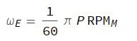
I’m guessing one of these is a mistake?
Tried what you suggested but no improvement to the power limit - CSSW becomes saturated at about 1000W.
I also tried running the RCBenchmark with USB disconnected (from the Komar) but, again, couldn’t get any response with PWM control.
Here is the list of parameters so far. Please advice.Komar MN5212 Config.yml (2.2 KB)
This is the correct formula. Just pi because P is the number of poles. If there were a number of pole pairs, then there should be 2pi. Corrected. Thanks.
Could you show the Kucher window when it’s saturated?
Hi Dmitry,
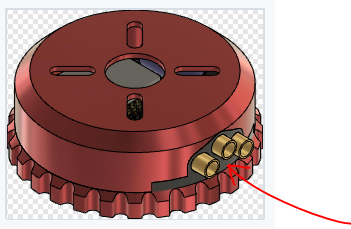
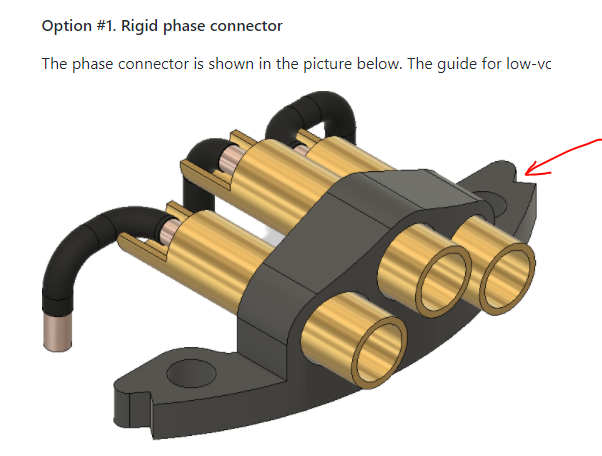
I will run a test shortly and send you a screenshot as requested. In the meantime can you please share a .step file of the bullet connector 3D-printed holder?
Additionally, do you have any more ideas why the ESC would not run in PWM mode?
Hi Dmitry,
I recorded a video instead. See attached. Waiting for your inputs. https://forum.zubax.com/uploads/default/original/1X/58b5b35ad23acf1a8418162070739758aeef8a22.mp4
Hi George,
Try to increase the hysteresis of the field weakening turn-on speed m.fw_eangvel_hys. Now it set to 100, try 200 or 300. Otherwise, as you can see from the video, the field weakening mode is immediately turned off.
I would also recommend configuring based on more realistic speed and current values. Typically, the field weakening mode is used to increase the motor speed by 5-10% during maneuvers or takeoff. In your case, the maximum electrical angular velocity without field weakening is approximately 8000 rad / sec. The field weakening mode should be switched on at the electrical angular velocity of 7500 rad / s. Therefore, I would recommend to set the maximum electrical angular velocity to 8500-9000 rad/sec. The hardware phase current limit of the Komar is 100 Amps. The m.max_current parameter is preferred to set to this value therefore.The m.max_id_current parameter set to 20% of m.max_current value, i.e. 20 Amps. You can increase it later if the max required speed is not reached.
Hi Dmitry,
Tried your suggested changes but without much change.
Did 3 runs: First with m.fw_eangvel_hys at 200 second with 300.
Third, I increased the m.max_id_current to 30.
Please see attached video containing all 3 runs.
Looking forward to your response.
Regarding this message, can you please share the geometry as requested? Can’t find it on github.
I need to swap the bullet connectors from 5mm to 4mm versions so I would need to reprint the parts with a small edit.
HI George,
The 3d model is available in the Komar repository on Github. You can download the assembly from the gallery in the step format as well. The assembly contains all the parts, including the phase connector.
@georgepaschalis the m.fw_eangvel_hys still is not enough to maintain the speed. Try to set it to a big value to confidently activate the field weakening mode, 1000 for instance. You will be able to decrease it later after the m.fw_bemf_ctl_ki and m.fw_bemf_ctl_kp tuning.
Ok after a lot of efforts I got some pretty good results.
At 22.2V I went from: 6500rpm and 1040W to 7100rpm and 1500W.
I found that the hysteresis of the field weakening m.fw_eangvel_hys started to have no effect at a values higher than 1600.
Had to increase the flux weakening current m.max_id_current to 50A and voltage amplification m.fw_volt_boost to 1.5.
Tuning the m.fw_bemf_ctl_ki and m.fw_bemf_ctl_kp had little- to no effect.
Thanks for the help!
See attached video and parameters of the latest run.
2021-10-13_Komar MN5212 Config.yml (2.2 KB)
Hi Dmitry,
Regarding the following, please let me know once the firmware release is out.
We have managed to reproduce your issue. It looks like you have electromagnetic interference on the RCPWM control wires. Because of this, the firmware sets the emergency stop flag and stops the motor. We have fixed this issue in the firmware. The motor will now continue to spin if the correct RCPWM pulse arrives after a failure. We will try to release a new firmware version by next week.
Hi George,
We found another solution.
Please test with the following parameters values.
rcpwm.pulse.bot – 0.001
rcpwm.pulse.hyst – 2e-05
rcpwm.pulse.mid – 0.0015
rcpwm.pulse.top – 0.002
The motor should start spinning from 1.7-1.6 ms in forward and 1.3-1.4 ms in reverse direction.
If it doesn’t, then check the port, connection and pinout.
If the motor spins, then return back rcpwm.pulse.mid to 0.001, but wide the deadband via rcpwm.pulse.hys.
Apparently your rcpwm signal duration is not equal to 1 ms as you set in the config file (for example, 1.1 ms). The motor will not start if there are pending faults (e.g. loss of signal) until a zero setpoint is received. Since the minimum pulse width of the signal is outside the deadband, it will never get a zero setpoint and the motor will never restart. A wide deadband can solve this problem.
Hi Dmitry,
I will try what you suggested although I’m not planning to run the motor in reverse.
Also, my signal on RCBenchmark starts from 0.9ms so I don’t see why the ESC wouldn’t receive the minimum value.
As reminder, I get no response from the ESC in PWM at all.
I will come back o you shortly after the test.