Hi,
We are trying to get a motor tuned using our Mitochondrik ESC for use with a multi-rotor system.
The issue we are seeing is that we cannot get reliable stability at high frequency step changes. We are currently running this in voltage control mode, and are playing with the relevant parameters. The propeller is a 18.3" x 6.2. The motor is a 160KV 5008 sized motor.
As far as the specifications, this propeller is the maximum sized propeller that will go with this motor. Reducing propeller size, or reducing the motor KV both seem to fix this issue. However we have used this motor/propeller extensively in the past with generic ESCs with no issues at all.
These are the best set of settings we could make work - though the motor is still able to de-sync reasonably reliably when the input is changed sufficiently fast. Whilst the rate of change is suitably fast for flying, the stability is not sufficient - especially when external factors such as wind are at play. Reducing the voltage ramp further is likely to impact stability of the aircraft.
Kv / Vramp / curr_bw
160 / 35 / 0.167
For comparison, our tests were not able to make a lower KV motor, of the same dimensions, with the same propeller fail with far more aggressive settings:
Kv / Vramp / curr_bw
140 / 50 / 0.175
The behavior is identical between the mitocondrik, and a myxa, ruling out some hardware issue. On the front of it, it looks like the propeller is too large for this motor and cannot sufficiently increase or decrease speed of the motor. However, as mentioned, this has worked extensively in the past, and still works on generic ESCs. Is there anything we can try to gain stable operation in all scenarios? Or is there some fundamental reason this will not work on this system?
It is worth noting that our testing is essentially a sine wave between two setpoint values that increases in frequency, giving large and rapid variations of speeds. It is extremely aggressive, however it does highlight issues very quickly.
Hi @anon81208224, @pavel-kirienko. Any ideas here? this is somewhat time critical for us, we are going to need to move away from the mitochondrik/myxa if this cannot be resolved in short order. What further information can we provide?
First of all, I would recommend checking if there are any faults. In Kucher there is the faults counter. You can check if the fault counter doesn’t increase or you can check the logs. As the propeller is big, it requires more current during transients for accelerating and decelerating the motor. This, in turn, can cause the hardware faults and the motor desync.
If there are no faults, you can switch to rpm control mode and tune it for more aggressive characteristics as described here. Or you can stay in the voltage control mode and increase the o.ekf.q_id and o.ekf.q_iq parameters in small steps. But be careful not to lose stability in the continuous motor spinning. You can find more information about advanced tuning in this post.
The only errors we get are 0b00000001_01100001, which is too many stalls. Presumably because of all the stalls.
To be honest we do not use kucher at all, we are only using the UAVCAN GUI tool, as all the parameters are there there has not been any need to utilize the kucher tool, that and the Linux version still crashes on each key-press. Will the logs in Kucher help somewhat? This is something that I can set up and hopefully leave whilst the scripts run and test the motor.
We had a go at tuning the o.efk.q_id, and iq parameters, which made no obvious difference. Though it was very hard to tell if it did anything. Raising the parameters arbitrarily higher did not seem to make any difference. Can you give me an indication as to what “small steps” means in this context? 10, 100 1000? For reference, we doubled the default values, and had no obvious difference. Is there anything particularly special we have to do to make them take effect?
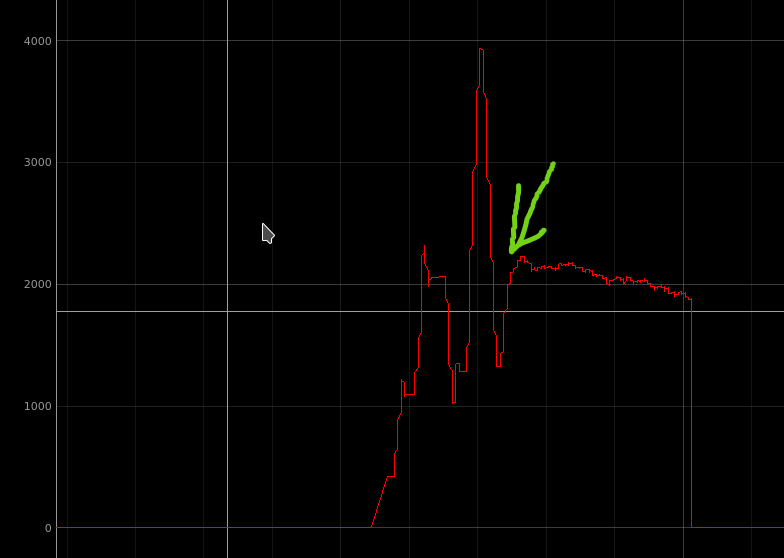
The RPM tuning is looking somewhat promising - though it also appears to have some strange issues when slowing the motor down - attached is a photo. The arrow is where a zero set-point was issued. You can see the motor carrying on for a length of time before it finally stops.
The point of Dmitry’s suggestion is that the controller may be stalling due to hardware protection kicking in. When that happens, the FET driver will temporarily override the control outputs issued by the microcontroller, making it very difficult for the control logic to keep tracking the state of the motor. The controller may not be able to recover after the protection is deactivated, causing the motor to stall, which then results in the error code you specified.
One way to check if this is indeed the problem is to simply increase the hardware protection threshold. It is set using a resistor on your custom ESC board:
The threshold current should be at least two times the peak phase current of the device to avoid unintentional activation of the protection. See also:
This appears to be a case of integrator windup caused by suboptimal tuning. If you want the motor to always stop once a zero setpoint is received (regardless of the outer control loops, specifically the RPM control loop), set ctl.hard_stop = true.
Ah, I misunderstood. We did run into this a while ago, however this does not have the same symptoms (motor simply losing power), nor the same warnings when it does kick in as reported by the ESC. On our Custom board we have changed that resistor to far higher than the phase current would ever be (in the order of 400A - the motor under full load consumes about 16A peaking at about 25A during transients). The issues are identical between this piece of hardware and the Myxa, so at this point we are simply using the Myxa as to rule out any other issues. I am not sure what this hardware limit is set to on the Myxa, but presumably it is high enough.
A perhaps different question that may help with tuning is what parameters or variables are related to each control mode, and which parameters require a zero setpoint or a full power cycle to take effect? There are a number (such as the ESC reverse parameter, and the control mode) that seem to only take effect once the ESC has been fully power cycled - this is through the uavcan_gui_tool, I am unsure if Kucher has any difference.
The motor characterization parameters such as resistance, pole count, etc. are used in all control modes. The current controller bandwidth ratio setting is also used in all control modes.
Dynamic settings are used depending on the control mode as follows:
Voltage control mode: only the voltage ramp is used (during spinup the current ramp is used briefly).
Current (i.e., torque) control mode: only the current ramp is used.
RPM control mode:
current ramp
RPM PID gains
electrical angular velocity limit
Parameters under m. (motor), mid. (motor identification), ctl. (controller), o. (observer) are reloaded when the motor is stopped (zero setpoint as you said). All other parameters require a restart. This is not dependent on the kind of software used.