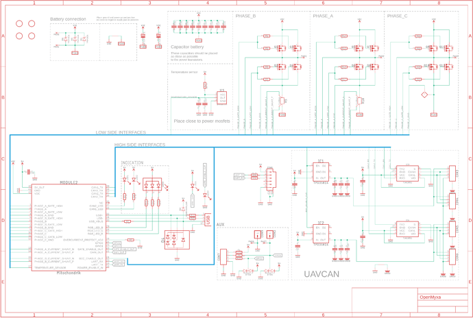
Schematic development
The schematic development is hardly interesting at all as it is basically a copy-paste straight from the datasheet. It is shown below:
Overcurrent protection
One matter that probably does need an explanation is overcurrent protection. Mitochondrik constantly monitors the voltage drop across the power transistors. It compares the voltage drop against the voltage on its oc_adj pin, which is set by an external resistor using the following formula:
where:
- R_\text{oc_adj} is the value of the protection trip level setting resistor [Ohm].
- R_\text{side} is the half-bridge side resistance [Ohm]. For example, in Komar, each half-bridge side is composed of two parallel transistors, each has R_\text{DS(on)} = 4.3\ \text{m}\Omega, which yields:
In the case of Komar, I_\text{trip} is set to 130 A, a level which is 2 times higher than the maximum continuous phase current but is within the safe operating range of the selected transistors.
From the equation above we obtain:
Last, but not least the RDS(on) of individual transistors changes with temperature considerably, and does the Itrip. At 85℃, Itrip will be approximately 1.5 times lower than it would be at normal operating temperature of 25℃; i.e. at around 90 A.
Gate resistors
Another sore subject is gate resistors, particularly their value and number. It is recommended to have series resistors for power transistor gates. In the case of parallel transistors, a separate gate resistor for each transistor should be used.
The main and only purpose of having the gate resistors is to eliminate ringing in the gate circuits. The ringing appears because PCB traces have stray inductance and transistor gates have stray capacitance and all this acts as an oscillating circuit. The lower the signal rise time is, the worse the oscillation gets. A gate resistor increases the rise time, thus reducing the oscillation. Steeper fronts, on the other hand, generally reduce the switching losses. The required gate resistance should be obtained by modeling the PCB parameters. Alternatively, trivial empirical methods could also be employed.
