Quick start guide for Myxa

This post is a tentative quick start guide for Myxa motor controllers. It assumes that the user has a GNU/Linux enabled PC; support for Windows is going to be added pretty soon as well. If you have any questions or concerns, please send us an email to info@zubax.com, or post right here in the comments.

The user is advised to have a basic understanding of the field-oriented motor control theory.

Overall, the setup procedure is as follows:

  1. Configure the USB connection.
  2. Download the Kucher GUI tool.
  3. Connect the motor to Myxa (if you need to reverse the direction of rotation later, swap any two phases). The motor should be disconnected from any mechanical load (propellers, thrusters, gearboxes, etc), otherwise, the automatic motor identification procedure may return suboptimal results. You must not touch the motor while identification is in progress for the same reason.
  4. Connect Myxa to a power supply, and then to your PC via USB.
  5. Launch Kucher, specify the number of poles and the rated current of the motor. Launch the motor ID procedure.

That’s it. Should be pretty straightforward to get started. Please see the following video for a more hands-on guidance:

Geometry and connectors

The images below document the placement and pinout of on-board connectors:

Bare board geometry:

Aluminum enclosure geometry:

1 Like

Okay, continuing with the quick start guide here.

Motor control modes

Myxa implements an advanced field-oriented motor control algorithm that features high efficiency and fast response, provided that the controller is configured properly. Myxa supports the following three major motor control modes:

  • Voltage control mode – in this mode, the controller modulates the specified quadrature axis voltage Uq, ignoring the quadrature axis current Iq, while maintaining the direct axis current Id close to zero. This mode imitates the behavior of a typical BLDC ESC.

  • Current (torque) control mode – in this mode, the controller modulates the specified quadrature axis current Iq, while maintaining the direct axis current Id close to zero. Since the torque of an electric motor is linearly dependent on the magnitude of the torque-generating current (i.e. the quadrature axis current Iq), this mode allows the controller to achieve constant torque irrespective of the angular velocity of the rotor (until the voltage modulator is saturated). This, in turn, can be used to modulate a nearly-constant thrust if the controller is used to drive a propeller or some other thruster.

  • Velocity control mode – in this mode, the controller runs an angular velocity control loop (which is based on a simple PI controller) on top of the current control loop described earlier. The controller maintains the requested velocity by regulating the torque. This control mode is typically used for variable pitch drives or multirotor UAV drives. This control mode is selected by default.

Some theory on motor control in the context of simple BLDC drives can be found in the Sapog Reference Manual.

Communication interfaces

The following interfaces are supported:

  • Single or doubly-redundant CAN busUAVCAN. The UAVCAN GUI Tool might come in handy. The implementation of UAVCAN in Myxa is largely equivalent to that in Sapog, so please refer to the Sapog Reference Manual for an in-depth description. The only major difference is that Myxa does not support automated ESC index assignment - it has to be configured manually.
  • Proprietary binary serial protocol over USB and UART. The protocol is built on top of Popcop; it features a strong data integrity protection and resilience to packet losses. This protocol is leveraged by the Kucher GUI tool; as Kucher is open source, you are encouraged to use it as an example and reference for building your own applications that interact with Myxa.
  • The industry-standard RCPWM, sometimes referred to as RC PWM or even RC PPM. This interface is flawed in many ways, so we generally discourage its use. Shall you choose to use it, you will need an adapter cable (shown below) that connects the pin GPIO1 of the Aux connector on Myxa to an RCPWM-compatible header as shown below.

Integration instructions for Myxa are not yet written; however, we have them for Sapog, and seeing as Myxa’s communication interfaces are largely similar to those in Sapog, we suggest our early customers to refer to the following guides, keeping in mind the differences in configuration parameters, which we’re going to review here next: Sapog BLDC motor control solution - Knowledge Base - Zubax Knowledge Base.

Configuration parameters

In this section, we’re going to walk through some of the most important configuration parameters available in Myxa. Most configuration parameters take effect virtually immediately or at the next use, so in most cases, it is not necessary to restart Myxa.

Common abbreviations:

  • eangvel - electrical angular velocity; always in electrical radian/second.
  • ctl - control.
  • ttl - time-to-live - the amount of time between the last command received from the given interface until the motor is stopped automatically.

Motor control

Motor control parameters are contained in the section m; for example, m.max_current. Some of the parameters in this section are deduced by Myxa automatically if they are not provided by the user. It is, therefore, necessary to reset all of the parameters in the group if you’re switching Myxa to a different motor; otherwise, the auto-deduced parameters will keep their old values.

All parameters in this group take effect when the motor is started or re-started. Restarting the whole device is not necessary.

  • m.num_poles - the number of magnetic poles on the rotor; equals the number of magnets on the rotor; always an even number.
  • m.max_current - rated phase current of the motor, in amperes (more on this later).
  • m.min_current - minimum current at which sufficiently stable operation of the drive is guaranteed. Deduced automatically from the previous parameter; can be changed by the user if necessary. You should lower this value if your application requires low-speed operation.
  • m.flux_linkage - magnetic flux linkage in weber; measured automatically.
  • m.resistance - phase resistance in ohm; measured automatically.
  • m.induct_direct - direct axis phase inductance in henry; measured automatically.
  • m.induct_quad - quadrature axis phase inductance in henry; measured automatically.
  • m.min_eangvel - minimum electrical angular velocity, in electrical radian/second, at which sufficiently stable operation of the drive is guaranteed. You should lower this value if your application requires low-speed operation.
  • m.max_eangvel - maximum rated electrical angular velocity, in electrical radian/second. Raise this value if the motor does not reach required speed levels in the RPM control mode.
  • m.current_ramp - the maximum rate of change of the quadrature current setpoint (Iq), in amperes per second.
  • m.voltage_ramp - the maximum rate of change of the quadrature voltage setpoint (Uq), in volts per second. Generally, values above 10 V/s require a higher setting of m.current_ctl_bw, otherwise the stability can be compromised.
  • m.eangvel_accel - the maximum permitted acceleration, in electrical radian per second per second. It is likely that this value will need to be increased for multirotor drives.
  • m.eangvel_decel - the maximum permitted deceleration, in electrical radian per second per second. It is likely that this value will need to be increased for multirotor drives. Do not exceed 10000 radian/second^2.
  • m.eangvel_ctl_kp - P gain of the RPM PID controller. Units: ampere*second/electrical_radian.
  • m.eangvel_ctl_ki - I gain of the RPM PID controller. Units: ampere/electrical_radian.
  • m.eangvel_ctl_kd - D gain of the RPM PID controller. Units: ampere*second^2/electrical_radian.
  • m.current_ctl_bw - the bandwidth multiplier of the current control loop; unitless. At very high ramp settings, especially in the voltage control mode, this parameter should be increased in steps of 0.02. Generally, values up to 0.1 are safe.

BEC

There is only one parameter in this group; it is valid only for Myxa B: bec.can_pwr_on. It defines whether the BEC (battery elimination circuit) power output is enabled or not. The parameters takes effect immediately.

UAVCAN

All parameters in this group take effect after a reboot.

  • uavcan.node_id - the UAVCAN node ID. If set to zero, which is the default, Myxa will attempt dynamic node ID allocation.
  • uavcan.esc_index - the index of this ESC on the vehicle. Set to zero by default; must be configured manually.
  • uavcan.esc_ttl - deadman switch timeout, in seconds.
  • uavcan.esc_rcm - RCM stands for “ratiometric control mode”. This setting defines which control mode to use when interpreting the message uavcan.equipment.esc.RawCommand:
    • 0 - current control mode
    • 1 - RPM control mode
    • 2 - voltage control mode

Beware that Myxa does not support automated ESC index assignment. The parameter uavcan.esc_index must be configured manually.

RCPWM

All parameters in this group take effect when the RCPWM signal is connected, i.e. in order to apply new parameters, disconnect the RCPWM cable from the device and then connect it back at least 0.1 seconds later. An exception is rcpwm.enable - out of safety considerations, this parameter takes effect only after reboot.

The basics of RCPWM are explained in the relevant section of the Sapog reference manual, and some useful information is also provided on Wikipedia.

  • rcpwm.enable - whether to enable the RCPWM interface. Requires reboot.
  • rcpwm.pulse.bot - minimum duration of the RCPWM pulse, in seconds.
  • rcpwm.pulse.mid - duration of the RCPWM pulse that is treated as a zero setpoint, in seconds; i.e. the motor will be stopped.
  • rcpwm.pulse.top - the maximum duration of the RCPWM pulse, in seconds.
  • rcpwm.ttl - deadman switch timeout, in seconds.
  • rcpwm.ctl_mode - which control mode to use with RCPWM:
    • 0 - current control mode
    • 1 - RPM control mode
    • 2 - voltage control mode (default)

By default, the range parameters are set up as follows:

  • rcpwm.pulse.bot - 1 ms
  • rcpwm.pulse.mid - 1.5 ms
  • rcpwm.pulse.top - 2 ms

Which implies that the motor will be stopped when the pulse is 1.5 ms long; run forward if the pulse is longer than that, and reversed if the pulse is shorter than that. In order to configure unidirectional operation, set rcpwm.pulse.mid to 1 ms.

Advanced tuning

In certain scenarios, with some motors, manual tuning of the control system may be required in order to achieve optimal performance.

  1. Run the motor with a load attached in the current control mode. Increase the current setpoint until the motor stops accelerating. Decrease the current setpoint a bit and ensure that the drive operates stably. If the motor speed is not stable or if the motor is restarting repeatedly, or if the motor phase currents or DC current are too high:
    1.1. decrease the parameter m.flux_linkage in 0.00001–0.0001 Wb steps;
    1.2. decrease observer parameters towards o.ekf.q_id = 10000 and o.ekf.q_iq = 30000 until a stable and smooth operation in all range of current setpoints is achieved.

  2. If uncommanded speed variations or a general instability are observed, do the following:
    2.1 set the parameter o.ekf.q_eangvel to 3000000;
    2.2 if the previous operation didn’t help, decrease the parameters m.voltage_ramp and m.current_ctl_bw.

  3. If you need to improve the step response characteristic in the voltage control mode, increase the parameters m.voltage_ramp up to 50 V/s and m.current_ctl_bw up to 0.1 in small steps.

  4. If you need to tune Telega in the speed control mode, first of all, set the maximum speed for your application. Apply the minimal battery voltage to the ESC. Spin the motor up to maximum speed by sending a 100% setpoint in the Ratiometric Voltage Control mode or Ratiometric Current Control mode. Read the value of the parameter motor.electrical_angular_velocity and assign this value to the parameter m.max_eangvel. This change will ensure that the speed controller will never reach saturation in your application and the speed will be always controllable. After that, you should tune the speed controller as described.

Is it recommended to perform the motor identification for every motor, or can the parameters be reused for motors of the same type? Assuming the motor manufacturer has reasonably good quality control.

@Anubis it is not necessary to perform motor identification per every motor if motor parameter variations do not exceed the following limits:

Parameter Deviation
Flux linkage 0.3%
Inductance 1%
Resistance 1%

Some decent motors may not require identification at all (e.g. Maxon, Anaheim), you can just copy-paste the motor parameters from the datasheet provided by the vendor. Low-cost motors and motors with poor repeatability (e.g. T-Motor, Tarot, KDE, Scorpion, and so on) always require identification for every motor.

1 Like

Using Myxa in multirotor aircraft

This section has been updated for Telega v0.5 and newer. If you are using an older version, consider updating the firmware.

By default, Myxa’s control loops use fairly conservative settings which result in slow speed response characteristics. These settings are optimized for applications where fast response is not required by design (e.g. electric aircraft and submarines). Other applications, such as multirotor aircraft, may require faster response, in which case Myxa’s settings will require adjustments.

In order to improve the response characteristics of the speed control loop, perform the following adjustments:

  • Set the acceleration rate to 15 000 ~ 20 000 electrical radian per second per second, depending on the needs of your application.
  • Set the deceleration rate close to 10 000 electrical radian per second per second or lower (higher values should be avoided).
  • Set the maximum current to 1.5 times of the maximum continuous current of the motor, but not higher than 40 A (or whatever is the maximum peak phase current for your controller).
  • Set the P and I gains of the PID controller (m.eangvel_ctl_kp, m.eangvel_ctl_ki) as described below; set the D gain (m.eangvel_ctl_kd) to zero.
  • Set the linear feedforward coefficient load.linear_coef to zero, set the quadratic feedforward coefficient load.square_coef as described below.

The relationship between electrical angular velocity and mechanical RPM is defined as follows:
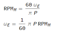
RPM-omega
where:

  • RPMM - mechanical RPM,
  • ωE - electrical angular velocity, in radian per second,
  • P - number of rotor poles.

The transfer function of the speed PID controller can be approximated as follows:


where:

  • A - current setpoint [ampere]
  • Kp - proportional gain [ampere*second/electrical_radian]
  • Ki - integral gain [ampere/electrical_radian]
  • Kd - integral gain [ampere*second2/electrical_radian]
  • n - sample index
  • ωE - electrical angular velocity [radian/second]
  • ΩE - electrical angular velocity setpoint [radian/second]
  • TPWM - PWM period [second]

The feedforward torque is computed as follows:

\tau_\text{ff} = \omega^2 c_2 + \omega c_1

Where \omega is the mechanical angular velocity in radian/second, c_1 is load.linear_coef, c_2 is load.square_coef.

The tuning amounts to setting three parameters: m.eangvel_ctl_kp, m.eangvel_ctl_ki, and load.square_coef. There is a helpful spreadsheet that automates the tuning process (make a copy and edit that):

Enter the required numbers and adjust the performance by changing the damping factor δ if necessary (if unsure, leave the default value). If you require any further guidance or if your propeller is not listed in the spreadsheet, please, reach out to us either via this forum or via support@zubax.com.

Field weakening tuning

  1. Set the value of weakening current m.max_id_current = 20…40% of m.max_current.

  2. Set the maximum allowable electrical angular velocity of the motor. For example, if you want to set the max speed to 6000 rpm, set m.max_eangvel = 6000/60 * m.num_poles * pi. In the field weakening mode, the ratiometric RPM control mode is used. The setpoint value is normalized to m.max_eangvel.

  3. Enable the field weakening feature: ctl.field_weaken = true The field weakening mode will be automatically activated when the motor voltage is close to the operating voltage limit.

  4. Tune the BEMF controller if there is poor response in the field weakening mode. Increase m.fw_bemf_ctl_ki and m.fw_bemf_ctl_kp.

  5. If you are using the voltage control mode (uavcan.esc_rcm = 2 or rcpwm.ctl_mode = 2), there may be abrupt speed (thrust) variations at values close to the maximum speed when the field weakening mode is activated. If these variations are significant, it is recommended to use the ratiometric RPM control mode (uavcan.esc_rcm = 1 or rcpwm.ctl_mode = 1).

Spinup tuning

Starting the motor from standstill is challenging for any sensorless drive, Myxa is no exception.

When commanded to start the motor, Myxa activates the current control mode first, regardless of the commanded control mode - Myxa will switch to the desired mode once the motor is started. The initial current setpoint is set to the value of m.spup_curr_begn, in amperes, where begn stands for “beginning”. Once the spinup process is initiated, Myxa will linearly ramp the current towards the second ramp endpoint defined by the parameter m.spup_curr_end. The duration of the ramp is defined by the parameter ctl.spinup_durat, in seconds; however, Myxa can abandon the ramp early and switch to the normal operating mode if it deems so appropriate. The ramp is illustrated in the following figure:

The ramp can be negative as well:

Myxa will abandon spinup and restart from scratch if the motor did not reach stable operation by the end of the ramp.

Observe also that if the motor is already spinning when the ramp is activated, Myxa will detect that, and skip the ramp, switching to the normal operating mode immediately. This behavior ensures that the motor can be restarted quickly and reliably if the rotor is already spinning in the correct direction. However, high settings of the initial current setpoint can somewhat interfere with this behavior.

In the firmware v0.2, the default values are set as follows:

  • ctl.spinup_durat = 1.5
  • m.spup_curr_begn = 0.2 × m.max_current
  • m.spup_curr_end = 0.025 × m.max_current

If the motor does not spin up sufficiently quickly, or if the rotor freezes for a few seconds before starting, it is recommended to alter the configuration parameters as follows:

  • ctl.spinup_durat = 0.5
  • m.spup_curr_begn = 0.5 × m.max_current
  • m.spup_curr_end = 0.05 × m.max_current

The proposed configuration defines a reverse (negative) current ramp. If the motor overshoots to a high speed after spinup and it is considered unacceptable, the initial current value m.spup_curr_begn can be reduced as necessary. Usage of constant current ramps (i.e., when the endpoints are equal) is likely to lead to substandard performance and therefore not recommended, because the rotor state observer requires some current gradient in order to deduce the initial position of the rotor.

Note that the following constraints must be met, otherwise Myxa may reject the configuration as invalid:

  • m.spup_curr_begnm.max_current
  • m.spup_curr_endm.max_current
  • m.min_current < m.max_current
  • 0.1 ≤ ctl.spinup_durat ≤ 60

Power balance explained

A popular source of confusion when using Telega (or vector control drives in general) is the complicated relationship between the DC link current (the current that flows between the battery and the motor controller) and the phase current (between the controller and the motor).

Reviewing the system in terms of power conversions helps to eliminate the confusion.

The DC input power PDC is simply the product of DC voltage and DC current:

PDC = UDC IDC

The active power delivered to the motor can be expressed in terms of the rotating DQ system quantities (simplified, ideal conditions assumed):

PM = 3/2 UQ IQ ⇔ ID = 0

The reactive power is not of interest in this case, so it can be ignored safely.

In general, assuming negligible losses, the following holds true:

PDC ≈ PM ⇔ Ploss ≪ PM

Therefore:

UDC IDC ≈ 3/2 UQ IQ ⇔ Ploss ≪ PM, ID = 0


It is also helpful to mentally picture the motor controller as a step-down DC-DC converter on steroids; for a DC-DC converter the following is valid:

Uin Iin ≈ Uout Iout

Notice the similarity with the above equations.

The windows version of Kucher is missing from your FTP server.

The Windows version has not yet been released, sorry. We’re going to post an announcement here when it is available.

I have a step model for Myxa B. I will just leave it here.
MYXA B.step (10.8 MB)

1 Like

A post was split to a new topic: Myxa response tuning

Rejoice, Telega v0.2 is available! Download the binary from the file server. The firmware can be updated via CAN using the UAVCAN GUI Tool.

Changes from v0.1:

  • Improved stability, especially during rapid acceleration and deceleration.
  • Field weakening (flux weakening); please contact us for setup instructions – official documentation will be released later.
  • Fixed the power-up issue where the device would refuse to boot unless the power supply voltage slope is steep enough.
  • RPM control loop stability improvements.
  • Motor characterization improvements.
  • Faster boot-up – approx. 200 milliseconds from power on to ready to run.
  • Faster and more robust spin-up process.
  • Motor self-test at power-up is not performed by default; can be enabled via ctl.pwron_slftst.
  • Selectable spool-down policy: either controlled braking (default) or immediate power stage deactivation (set ctl.hard_stop).
  • Parameter renamings:
    • m.spup_current_lm.spup_curr_begn
    • m.spup_current_hm.spup_curr_end
    • m.phi_milliweberm.flux_linkage (change of units: milliweber → weber)
    • m.rs_ohmm.resistance
    • m.ld_microhenrym.induct_direct (change of units: microhenry → henry)
    • m.lq_microhenrym.induct_quad (change of units: microhenry → henry)
    • m.eangvel_rampupm.eangvel_accel
    • m.eangvel_rampdnm.eangvel_decel

The quick-start entries above have been updated to match v0.2. If you still care about v0.1, use the edit history to reach the outdated entries.

Proper documentation will be available with Mitochondrik, stay tuned. We are hideously behind the schedule, but there are good reasons for that – testing takes time, and certain complex features (such as flux weakening) require a lot of effort to implement and validate. Our current focus is stabilization and documentation.

On a related note, Telega v1.0 will be equipped with UAVCAN v1.0; read more here: Stockholm Summit recap - Development & Maintenance - OpenCyphal Forum.

2 Likes

Any updates on Windows version? I see posts from early 2018 saying it will be available soon, but I don’t see it in the file directory.

Still nothing so far. Will post when available.

A post was split to a new topic: [Myxa] Current limiting behavior

There are few more parameters available now in v0.3. Could you please provide a description of them?

Telega firmware v0.3 is now available for download from the file server. The firmware can be updated via CAN using the UAVCAN GUI Tool.

Changes from v0.2:

  • The maximum no-load motor speed is increased by 18-25% (depending on the motor KV value).
  • The motor d-axis and q-axis currents and voltages are published in uavcan.protocol.debug.KeyValue UAVCAN messages. Keys are “idf”, “iqf”, “udf” and “uqf”.
  • Fixed the switching issue between voltage and speed control modes during field weakening activation and deactivation.
  • Fixed the motor speed saturation issue at 80-90% setpoint value in the ratiometric voltage control mode.
  • Introduced new parameters to improve motor characterization:
    • mid.phi.curr_bw - the current loop bandwidth for the motor flux linkage detection procedure.
    • mid.l.curr_bw - the current loop bandwidth for the motor inductance detection procedure.
  • Parameter renamings:
    • ctl.fw_v_boostm.fw_volt_boost .

Telega v0.5 is now available; please read the announcement here: Telega v0.5 is released

When migrating from an earlier version, be sure NOT to migrate the PWM frequency setting vsi.pwm_freq. Keep it at the new default value of 32000.