
“FluxGrip Pro Max: The best got even better.”
Introduction
If you’re reading this you’ve probably recently purchased (or are planning to purchase) a FluxGrip magnet. This guide is meant to serve as an entrypoint for new users of FluxGrip; we will cover most of the common use cases so you can get up and running as fast as possible.
Note that this is meant to be a practical guide, if you’re looking for detailed technical information regarding FluxGrip, please go to fluxgrip.zubax.com.
Which model?
Before we continue, let’s first discuss the models of FluxGrip which are available:
| Interface | FG401M | FG401MA | FG402M |
|---|---|---|---|
| Cyphal/CAN |  |
|
|
| DroneCAN | |
|
|
| Analog (Voltage level) |  |
|
|
| Analog (PWM) | |
|
|
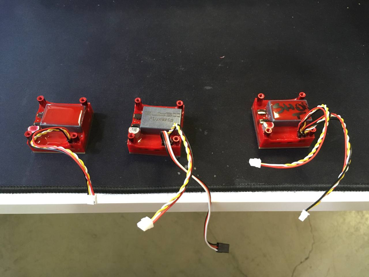
From left-to-right: FG401M (1x CAN), FG401MA (1x CAN, Analog) and FG402M (2x CAN).
Please ignore the messy table and writing on the magnets, just focus on the connectors
The only difference between the models are their interfaces, hardware-wise they’re all exactly the same. This means that the only decision you’ll need to make is whether you want to be able to control the magnet using CAN or through an analog signal.
If you’re going the CAN route, congrats, that’s the best way to go. You will also need the following:
- 1x CanFace CF1 (you could use your own CAN adapter but ours is better, more on this later)
Optional, but recommended:
- 1x CanSplit
- 1x Micro CAN Cable
If you’re going the analog route you’ll need to source an Arduino, a breadboard, jumper wires; stuff like that.
Powering FluxGrip
First things first: power. FluxGrip can be powered either through the CAN power lines, or through Analog power.
CAN Power
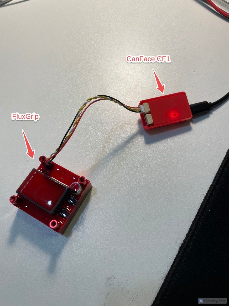
Assuming you have a CanFace CF1, you can power the magnet straight from USB by connecting FluxGrip to CanFace and CanFace (through USB) to the computer. There is one caveat.
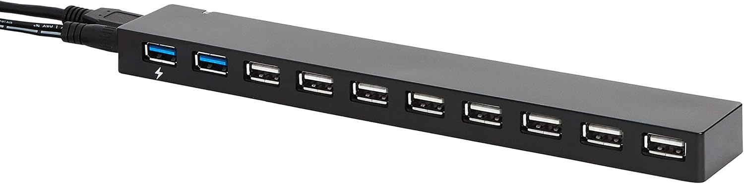
Even though all USB ports are created equal, some are more equal than others and so power available might differ between different USB ports. In rare cases the USB power will not suffice to turn the magnet on, which will then trigger a reboot and/or fault condition. If this happens, the easiest workaround is to use an externally powered USB hub, which will usually provide enough power.
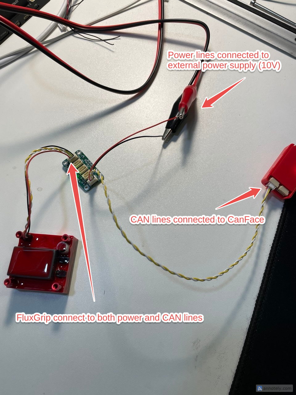
For an even better solution, use a CAN bus splitter and connect the power lines of CAN to an external power supply set to 10V (allowed range is 5-24V). Like so:
Warning
Note that CanFace only connects to the CAN lines (white and yellow), while the power lines (black and red) are cut and connected to the external power supply. If you connect the power lines to CanFace CF1 directly while it is powered by 10V you will damage it.

The benefit of this setup is that due to more power being available, the magnet is able to switch faster.
Analog Power
This is simple enough: connect the Red/Black (VDD/GND) to power source between 5-30V, I would recommend 10V for starters. For more details see the Analog Control section
Controlling FluxGrip
The next step is actually controlling the magnet, this can be done in a couple of different ways, which we will explain in the next sections. Like before these are split between CAN and Analog interfaces. Please use the outline of the right to jump to the relevant section, if you’re unsure, I would recommend to use Cyphal, which is by far the easiest way to get started.
CAN Control
Cyphal
- Connect: PC ↔ CanFace ↔ FluxGrip
- Open cyanide.zubax.com
- Click Connect SLCAN
- A window will pop up asking to select a Serial port
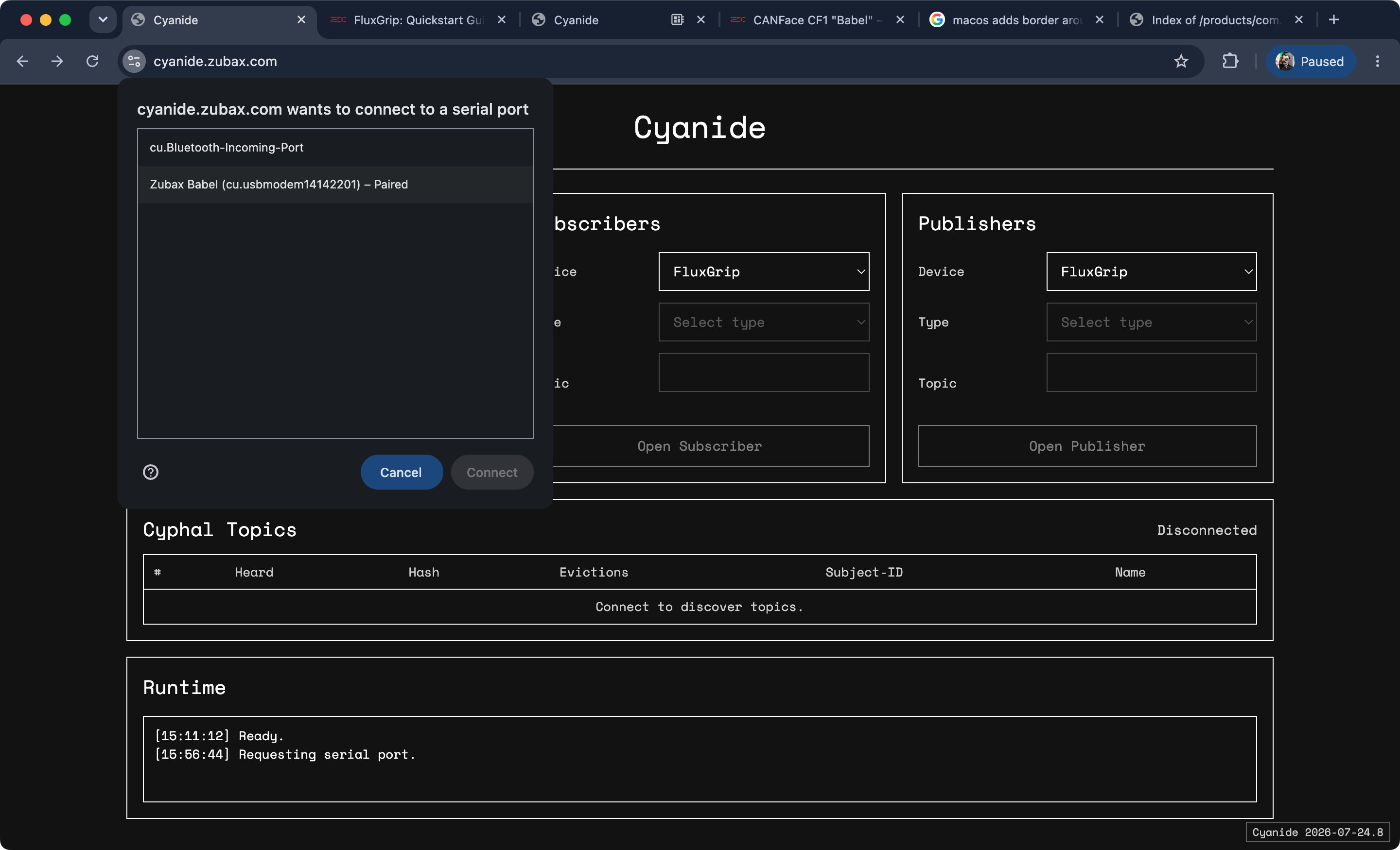
Select the “Zubax Babel” (old name of CanFace) one and Connect.
Tip
If you’re on Linux, there is a likelihood that permissions won’t allow the browser to interact with serial ports. Execute the following commands to make the USB ports accessible from the browser:
sudo wget -O /etc/udev/rules.d/99-usb-serial.rules "https://gist.githubusercontent.com/maksimdrachov/52a52db246684ca42fad98281721cca7/raw"
sudo udevadm control --reload-rules
sudo udevadm trigger
Once connected you should see three topics show up: manage, command, and feedback. These are topics which can be used to observe/control/configure the magnet.
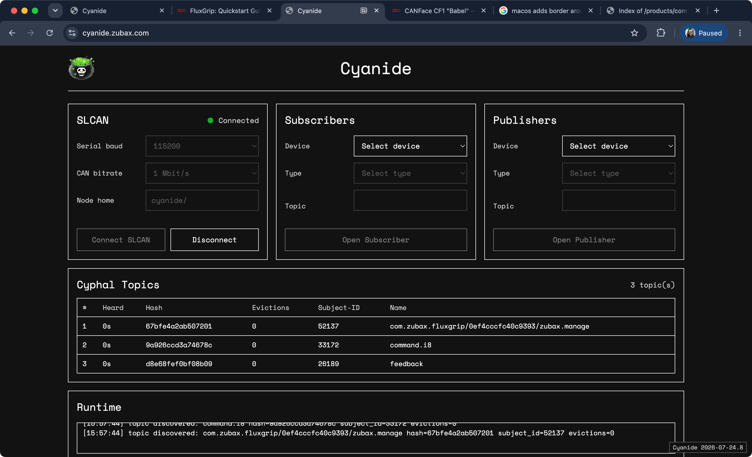
To turn the magnet on/off, you will need to use the command topic.
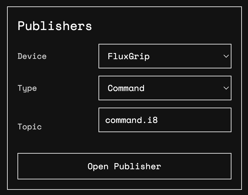
Then select the ON command from the dropdown menu and Publish.
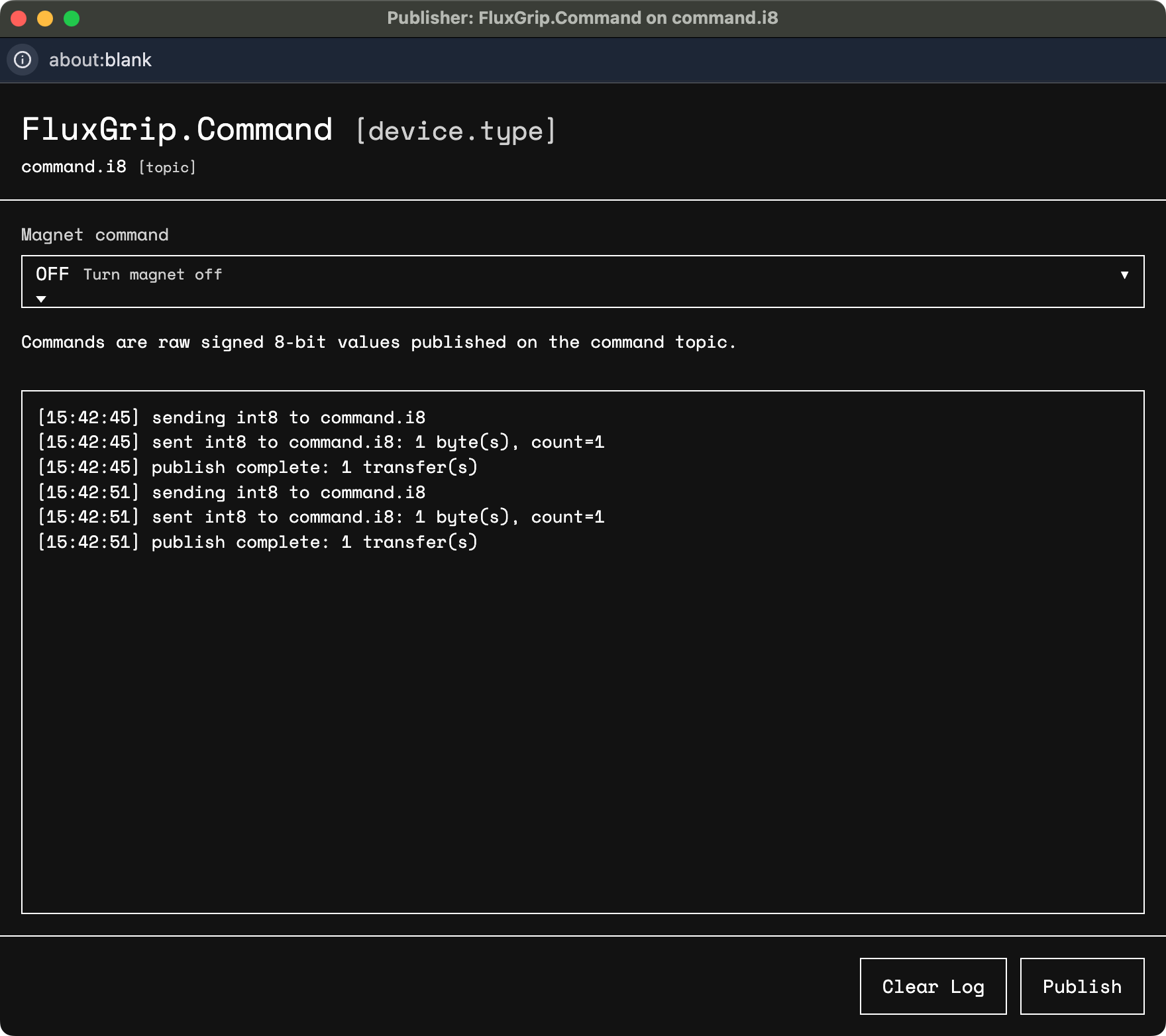
After a couple of seconds the magnet should be magnetized.
DroneCAN
If you’re using DroneCAN, there is a high likelihood this is because you’re relying on ArduPilot or PX4. To help you out we have two guides which cover exactly these use cases:
Analog
RC PWM
RC PWM is an industry-standard interface that is used literally everywhere – flight controllers, robotic submarines, low-cost robotic arms,…
The setup looks as follows (grey/white is the Analog input/control; red and black are, respecitively, power and ground):
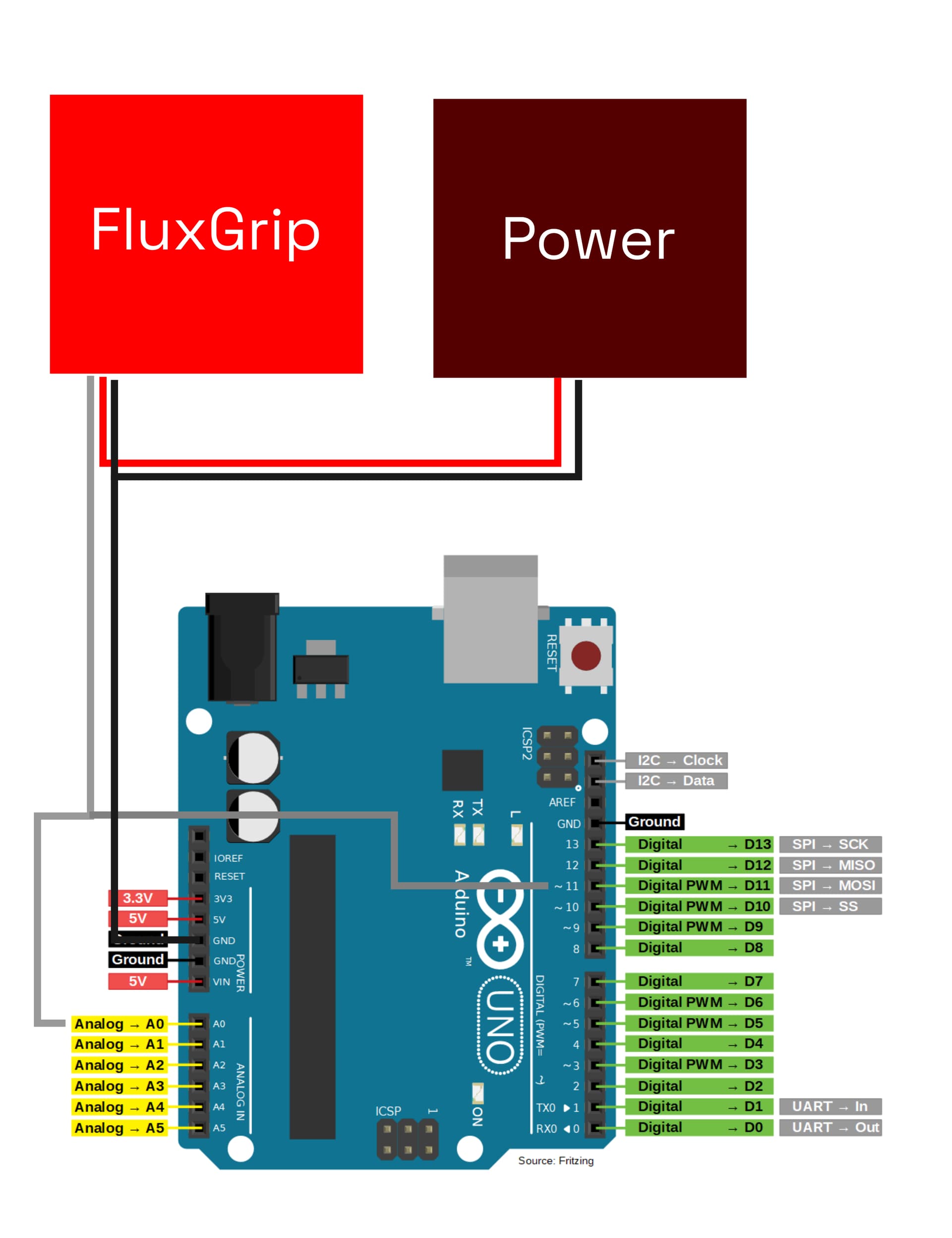
An external power supply (5-30V) will likely be needed as the Arduino may not be able to provide the necessary power.
The Arduino code looks as follows:
// General
constexpr int BAUD_RATE = 9600;

// Analog Feedback related
constexpr int ANALOG_PIN = A0;
constexpr float REFERENCE_VOLTAGE = 5.0;
unsigned long previousMillis = 0;
constexpr unsigned long FEEDBACK_INTERVAL = 1000;  // 1s

// PWM Control related
constexpr int PWM_PIN = 11;  // D11

namespace analog_feedback {
float read() {
  int analogValue = 0;
  float voltage = 0.0;

  analogValue = analogRead(ANALOG_PIN);
  voltage = (analogValue * REFERENCE_VOLTAGE) / 1023.0;

  return voltage;
}
}  // namespace analog_feedback

namespace pwm_control {
// Frequency PWM = Clock / (Prescaler * 255)
//               = 16,000,000 / (256 * 255) = 245 Hz ~= 250 Hz
// Period = 1/250 = 4 ms
// OFF:   requires between 0.8-1.2 ms -> 25% duty cycle = 1.0 ms
// ON:    requires between 1.6-1.9 ms -> 45% duty cycle = 1.8 ms
// FORCE: requires between 2.1-2.5 ms -> 55% duty cycle = 2.2 ms

namespace command_off {
const uint8_t dutyCyclePct = 25;
}  // namespace command_off
namespace command_on {
const uint8_t dutyCyclePct = 45;
}  // namespace command_on
namespace command_force {
const uint8_t dutyCyclePct = 55;
}  // namespace command_force

void leaveFloating() {
  pinMode(PWM_PIN, INPUT);
}

void setPWM(uint8_t dutyCyclePct) {
  pinMode(PWM_PIN, OUTPUT);

  TCCR2A = _BV(COM2A1) | _BV(COM2B1) | _BV(WGM21) | _BV(WGM20);
  TCCR2B = _BV(CS22) | _BV(CS21); // Clock divided by 256

  OCR2A = 255 * (uint32_t) dutyCyclePct / 100; // 255 is 100% duty cycle
}

void setForce() {
  pinMode(PWM_PIN, OUTPUT);
  setPWM(command_force::dutyCyclePct);
  delay(100); // 100ms
  leaveFloating();
}

void setOn() {
  pinMode(PWM_PIN, OUTPUT);
  setPWM(command_on::dutyCyclePct);
  delay(100); // 100ms
  leaveFloating();
}

void setOff() {
  pinMode(PWM_PIN, OUTPUT);
  setPWM(command_off::dutyCyclePct);
  delay(100); // 100ms
  leaveFloating();
}

}  // namespace pwm_control

void setup() {
  Serial.begin(BAUD_RATE);
  pinMode(ANALOG_PIN, INPUT);
  pwm_control::leaveFloating();
}

void loop() {

  /// ANALOG FEEDBACK ///
  // 1. Read the feedback voltage
  // 2. Print the current state of the magnet
  // 3. Repeat once every second
  unsigned long currentMillis = millis();
  if (currentMillis - previousMillis >= FEEDBACK_INTERVAL) {
    previousMillis = currentMillis;

    float voltage = analog_feedback::read();
    if (voltage >= 1.40 && voltage <= 1.90) {
      Serial.print("Magnet state: UNKNOWN\n");
    }
    else if (voltage < 0.5) {
      Serial.print("Magnet state: OFF\n");
    }
    else if (voltage > 3.0) {
      Serial.print("Magnet state: ON\n");
    }
    else
    {
      Serial.print("Voltage not within any expected range: ");
      Serial.print(voltage);
      Serial.print("V\n");
    }
  }

  /// PWM CONTROL ///
  if (Serial.available() > 0)
  {
    const char received = Serial.read();

    if (received == 'M') // Magnetize
    {
      Serial.print("Setting PWM to ON\n");
      pwm_control::setOn();
    }
    else if (received == 'D') // Demagnetize
    {
      Serial.print("Setting PWM to OFF\n");
      pwm_control::setOff();
    }
    else if (received == 'F') // Force
    {
      Serial.print("Setting PWM to FORCE\n");
      pwm_control::setForce();
    }

  }
}
When you turn on FluxGrip for the first time it will be in Detect state, which means that the current state of the magnet is yet unknown, this will be printed in the Serial ouput window:
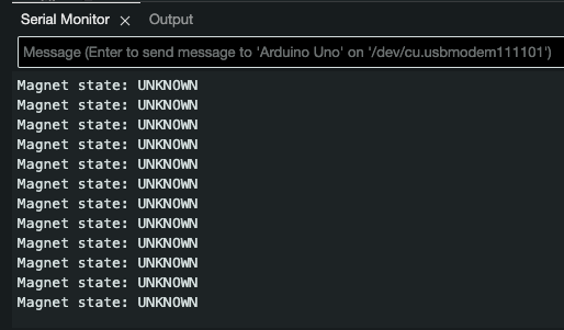
Using the Serial monitor you can send three different commands:
- ON: by sending
M - OFF: by sending
D - FORCE: by sending
F(this will turn on the magnet regardless of current state)
For example, sending M results in the following:
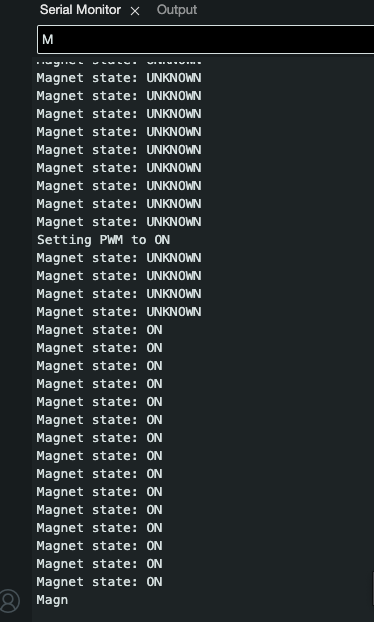
Voltage level
The setup is exactly the same as for RC PWM (see section above).
The Arduino code looks as follows:
// General
constexpr int BAUD_RATE = 9600;

// Analog Feedback related
constexpr int ANALOG_PIN = A0;
constexpr float REFERENCE_VOLTAGE = 5.0;
unsigned long previousMillis = 0;
constexpr unsigned long FEEDBACK_INTERVAL = 1000;  // 1s

// Voltage Control related
constexpr int VOLTAGE_PIN = 11; // D11

namespace analog_feedback {
float read() {
  int analogValue = 0;
  float voltage = 0.0;

  analogValue = analogRead(ANALOG_PIN);
  voltage = (analogValue * REFERENCE_VOLTAGE) / 1023.0;

  return voltage;
}
}  // namespace analog_feedback

namespace voltage_control {

void setOn() {
  pinMode(VOLTAGE_PIN, OUTPUT);
  digitalWrite(VOLTAGE_PIN, HIGH);
}

void setOff() {
  pinMode(VOLTAGE_PIN, OUTPUT);
  digitalWrite(VOLTAGE_PIN, LOW);
}

void setForce() {
  pinMode(VOLTAGE_PIN, OUTPUT);
  digitalWrite(VOLTAGE_PIN, HIGH);
}

}  // namespace pwm_control

void setup() {
  Serial.begin(BAUD_RATE);
  pinMode(ANALOG_PIN, INPUT);
  pinMode(VOLTAGE_PIN, INPUT); // Leave floating
}

void loop() {

  /// ANALOG FEEDBACK ///
  // 1. Read the feedback voltage
  // 2. Print the current state of the magnet
  // 3. Repeat once every second
  unsigned long currentMillis = millis();
  if (currentMillis - previousMillis >= FEEDBACK_INTERVAL) {
    previousMillis = currentMillis;

    float voltage = analog_feedback::read();
    if (voltage >= 1.40 && voltage <= 1.90) {
      Serial.print("Magnet state: UNKNOWN\n");
    }
    else if (voltage < 0.5) {
      Serial.print("Magnet state: OFF\n");
    }
    else if (voltage > 3.0) {
      Serial.print("Magnet state: ON\n");
    }
    else
    {
      Serial.print("Voltage not within any expected range: ");
      Serial.print(voltage);
      Serial.print("V\n");
    }
  }

  /// VOLTAGE CONTROL ///
  if (Serial.available() > 0)
  {
    const char received = Serial.read();

    if (received == 'M') // Magnetize
    {
      Serial.print("Setting Voltage to ON\n");
      voltage_control::setOn();
    }
    else if (received == 'D') // Demagnetize
    {
      Serial.print("Setting Voltage to OFF\n");
      voltage_control::setOff();
    }
    else if (received == 'F') // Force
    {
      Serial.print("Setting Voltage to FORCE\n");
      voltage_control::setForce();
    }
  }
}
Note: the ON command requires a voltage between 2.5V and 3.8V, however Arduino does not have any DAC, so we’re just relying on 5V (which is a FORCE command) instead.
LED patterns
Magnet-related
- Magnet is in Detect state (Unknown): the default state upon turning on
- Magnet is ON
- Magnet is OFF
- Magnet is “Turning On”
- Magnet is “Turning Off”
CAN-related
- CAN is stable: LED on the left is solid, while LED on the right blinks whenever data is transmitted
- CAN is experiencing errors: LED on the left blinks, LED on the right might stukk blink when successfull transmission occurs!
- CAN is OFF: LED on the left is off
Note: this state can be triggered by shorting CAN H and L lines, it seems however that the CAN interface is trying to restore connection therefore it’s switching between the error and off state pattern for the LED.