I’d like to know more about the breaking and regenerative breaking behavior of Orel20 and Sapog firmware. We have eight Orel20 mounted on a fixed wing aircraft in open loop control mode. The flight velocity and small propellers requiresr to spin the engine at a fast rate to produce thrust, therefor it is quite easy for the propeller to enter windmilling state, especially in descent.
Three pictures are attached:
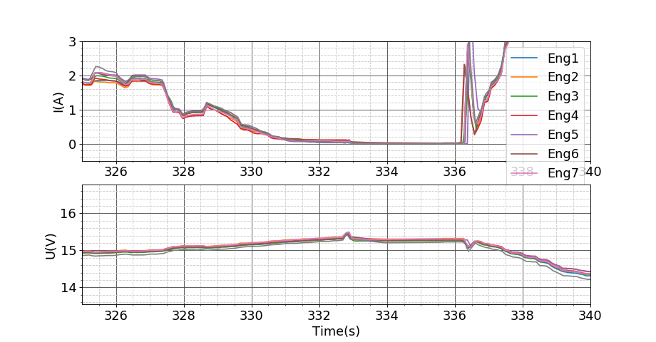
-Current and voltage measurement by Orel20
-Air velocity, calculated thrust and engine RPM
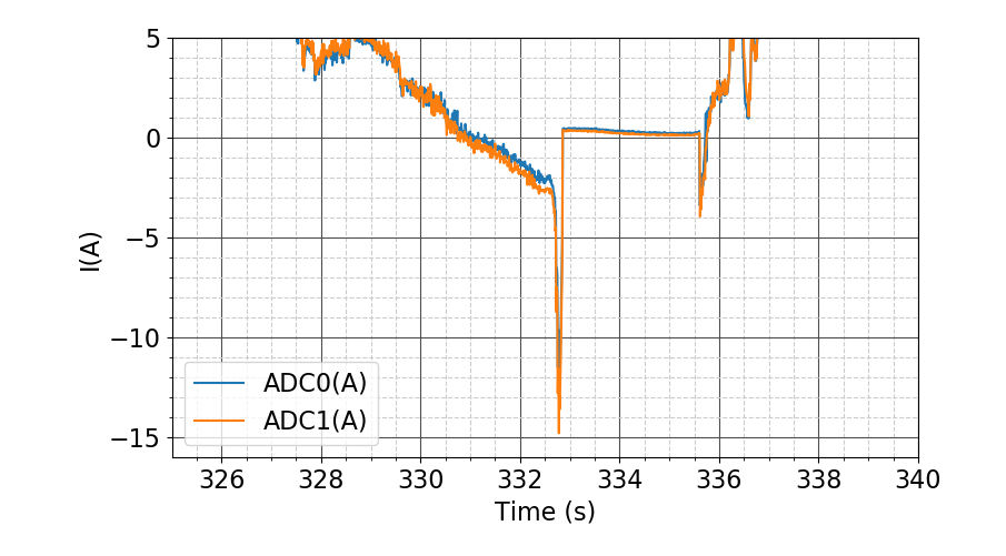
-ADC0/1: current measurements by power boards at the battery level
We have 2 batteries powering each 4 engines.
So far we identify one safe state:
-The propeller is producing negative thrust but the pilot keeps some control on the engine RPM and no power is produced (visible shortly at time=330s in the images). How does sapog manages the engine control in this case?
Lately we found a weird behavior:
-If the pilot sets throttle stick at 0%, high current spicks are returned to the power bus (shortly 14A!). Propellers are stopped shortly with a loud mechanical sound before being in what appears to be free-wheeling mode, despite the 0rpm measured by the ESC. And this is can be a cyclic behavior until the pilot throttles up again.
After reading both Orel20 and Sapog doc, I’m unable to explain these behaviors so I’d like to understand better:
-how does Sapog applies regenerative breaking and what is an “active free-wheeling”?
-as you can see in the pictures, measured current from Sapog doesn’t go negative and I don’t think this is only due to filtering. Is it possible to obtain the negative values as well (would be much useful for identification)?
-would it be possible to remove this regenerative breaking behavior or to control it better!(it is not really funny to hear that noise in flight) ?
-I understood that Sapog does not have breaking behavior (not regenerative) is that correct?
No special operating modes are applied in this case.
The abrupt stop and the large reverse current flow is probably due to a loss of synchronization.
When the motor is not driven (freewheeling), the speed is not measured and zero is reported.
Not sure why this could be cyclic. Is there any chance to reproduce this in a lab environment and capture the UART output from Sapog?
Regenerative braking is applied by modulating a lower output voltage than the induced back EMF. The resulting reverse current flow takes the energy out of the motor.
Active free-wheeling is the synchronous switching of both sides of a half-bridge so that the current flows through either of the two transistors instead of their flyback diodes (excepting the very short transients when the half-bridge is transitioning between the two stable states). The voltage drop on an open transistor is substantially lower than on a flyback diode, which results in a lower power dissipation.
Sapog uses a unipolar low-side current amplifier that is unable to capture negative currents, so it is a hardware limitation.
I think we need to understand the cause better. If you could reproduce this behavior in the lab, and describe your setup, it would help us investigate it.
Generally speaking, any electric brake is regenerative, because braking assumes the removal of mechanical energy from the motor by transforming it into electric energy, which is then either absorbed by the power supply (battery) or dissipated via a braking resistor. Certain basic low-power ESC apply braking by simply short-circuiting the motor with a particular duty cycle, but this approach is not scalable and is prone to damaging the drive.