We have two Zubax Myxa controllers with Télega motor control which we were attempting to use for power generation with two connected MN3110-15 780kv Tiger Motors. We set one ESC with a fixed RPM and used the other ESC to provide extra driving torque by increasing its current, therefore creating a regenerative braking phenomenon in the first motor.
The problem we faced is that by increasing the current in the “driving” motor only increased the generated power until a certain point and after that the power starts decreasing.
Is it possible that the control technology of Télega is not optimized for regenerative breaking and we should switch to another controller to be able to generate power efficiently?
Could you please describe your experiment in more detail, and also post your configuration parameters for the second Myxa?
Myxa is certainly not designed for power generation, but it doesn’t mean that it’s impossible to make it work there. The cause for the power decrease is unclear so more information is needed.
The goal of the experiment was to measure the maximum achievable power that our MN3110-15 780kv Tiger Motors can generate by using the Zubax Myxa ESC.
In every measurements we made, we used two motors connected by a coupling and two ESCs. The first ESC where we generate the power was set to 8000RPM by the speed controller. The other ESC was set to current control mode and the current was incremented by 2A in every measurement sets. This way the second ESC starts to provide an additional driving torque for the first motor around 1.1A and after this point the first motor needs to hold back the current controlled motor to keep the 8000RPM shared speed because of the coupling, therefore it starts to generate power (regenerative braking).
All tests were carried out until the RPM controlled motor could not provide enough torque to keep the shared speed (the first ESC reached its m.max_current limit), therefore the system started to accelerate and it was shut down.
We made 3 different tests by setting the m.max_current parameter to 15A, 35A and 45A in the ESC where we generate the power (The nominal rating for the motor is 26A so we didn’t try higher values). In our understanding this is the only parameter which influences the spin up.
The results can be seen in the following table (U=33.5V):
Driving current (A)
Generated power (W) (m.max_current = 15A)
Generated power (W) (m.max_current = 35A)
Generated power (W) (m.max_current = 45A)
2
9
9
9
4
27
27
27
6
44
43
43
8
58
58
58
10
70
70
70
12
Spin up
65
69
14
-
Spin up
Spin up
As it can be seen, none of the configurations could provide more than 70W. It seems like the FOC works fine at lower current values, however as the “driving power” increases, the FOC turns to be ineffective.
We assume that the PWM is not optimized for power generation which becomes the most visible at higher driving power. Our assumption is based on a same test carried out with a different type of ESC where we could reach 120W with the same test setup.
Do you have any suggestion what parameters can be changed in order to make any improvements to reach a higher power generation with the Zubax Myxa as well?
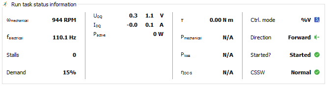
For a better understanding of the reasons, we need the value of Udq, Idq and mechanical speed of both ESCs at the maximum power level and with further power reduction at higher driving current. The required parameters can be found on the Run task status information Tab .
Since they are connected, the mechanical speeds will be identical in any case.
To observe the required parameters, the two Kucher GUIs were recorded for one measurement with a current limit of 35A in the following video.
The ESC in the right window is the one with RPM control mode (8000RPM), this is the one which is used later as generator.
The motor on the left is the driving one, it is set to current mode and it’s driving current is increased from 0A until 12.80A. At this point the other RPM controlled motor can’t hold the 8000RPM anymore and both motors spin up together and the test is shut down.
There is a slow motion about the spinning up part from 1:55 in the video.
Have you disconnected load from each motor during identification procedure? Try to tune a little bit (wit step 0.00002) m.flux_linkage parameter on the motor running in the RPM control mode.
Judging by the video, your assessment of electrical power seems to be based on the active power estimate. In any sensorless system, this estimate is imprecise because it is highly dependent on the accuracy of the rotor state estimate. I recommend focusing on the DC power instead, which is measured nearly directly.
I made the identification procedure, this time without any load.
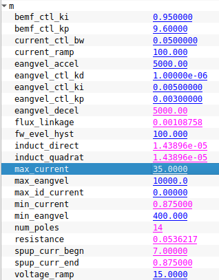
Before the identification the flux and the generated power:
m.flux_linkage:
Gen. power:
0.00108758
70W
After the identification:
m.flux_linkage:
Gen. power:
0.00109349
70W
Therefore it did not give any significant difference. After this I started to change the flux linkage value by the recommended step size of 0.00002.
Test nr.:
m.flux_linkage:
Gen. power:
0
0.00109349
70W
1
0.00107349
67W
2
0.00111349
72W
3
0.00113349
lost rpm estimation
4
0.00112349
lost rpm estimation
5
0.00111749
lost rpm estimation
6
0.00111349
73W
7
0.00111349
73W
Test nr. 1 is made by lower flux linkage which also decreased the generator performance.
From test nr. 2 the value was increased. With too big values (test nr. 3-5), the two RPM values were not the same anymore even though they were still connected, therefore the rpm estimation was wrong. This way the last stable state can be maintained by the flux value of 0.00111349.
Overall, there is a small increasing in the generated power value by increasing the flux linkage, however it is still not a significant improvement.
Is there any other parameter which could also change the performance of the ESC?
Thank you for the recommendation! In the video it is hidden unfortunately, however the DC power values were almost the same as the power values estimated from the q-d quantities during all the measurements. From now on I will only focus to the DC power!
I didn’t get any further interesting results since last time unfortunately.
With higher m.flux_linkage we managed to get a bit higher power generation
With higher m.max_current we managed to put a bigger pulling force to the generator, therefore we got again a little bit higher power generation
However, none of these 2 made significant difference, therefore we ended up saying that the Téléga-FOC control algorithm works probably perfectly in motoring mode but it is not very efficient for regenerative braking.
Hi Bertalan.
You encouraged us to create a test bench for reproducing your results in generator mode. After that we will tune and give you optimized parameters. Possibly, we will update Telega a little bit.
Back soon with the updates.