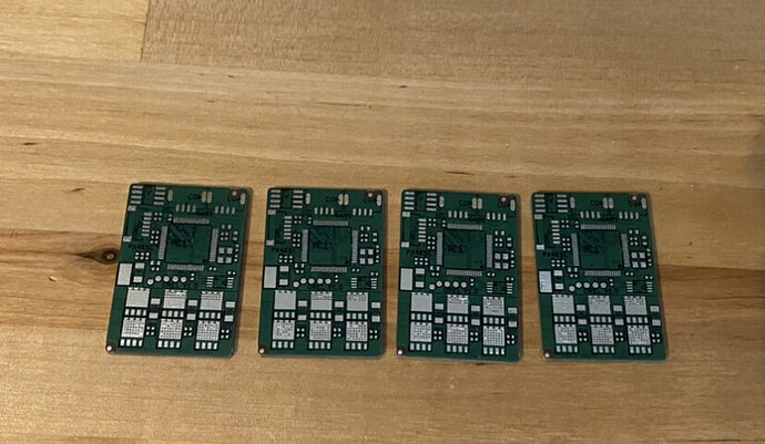
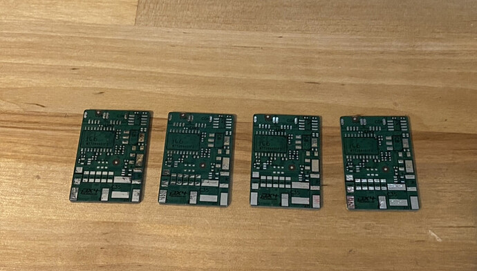
I have printed the Orel ESC pcb’s based on the reference design board files on github. One thing to note is that the BOM looks like it was compiled several years ago (before the pandemic supply constraints + chip shortage).
All of the components can now be found, albeit with some substitutions that I am not 100% sure about
- I was thinking of substituting the Infineon FETS with these: https://www.ti.com/lit/gpn/CSD18512Q5B
The TI FETS have the same dimensions as the Infineon ones and the footprint looks close if not identical.
- I could not find in the original BOM JST-GH 4 pin female surface mount. I did find an alternative that looks very close to the original footprint here: https://www.jst-mfg.com/product/pdf/eng/eGH.pdf
Notice the PCB design has the oval shaped pads on either side but the datasheet shows them as rectangular. Is this going to be problematic even if the pin spacing on the signal pads are the same?
-
The original crystal oscillator used is the schematic is generic, but I assume one like this could work given the dimensions, but would it need to be 3.3v tolerant? https://www.digikey.com/en/products/detail/txc-corporation/7M-24-000MAHV-T/5126384
-
I found this 5mOhms current shunt resistor but not sure if the footprint is correct, the listed one in the BOM is generic: https://www.digikey.com/en/products/detail/stackpole-electronics-inc/CSNL2010FT5L00/1788098
Last but not least the STM32F105RCT7. Is the 256KB of flash going to be adequate for the Sapog firmware? I plan to use these ESC’s in a Cyphal application on a multirotor: https://www.digikey.com/en/products/detail/stmicroelectronics/STM32F105RCT7/2214610
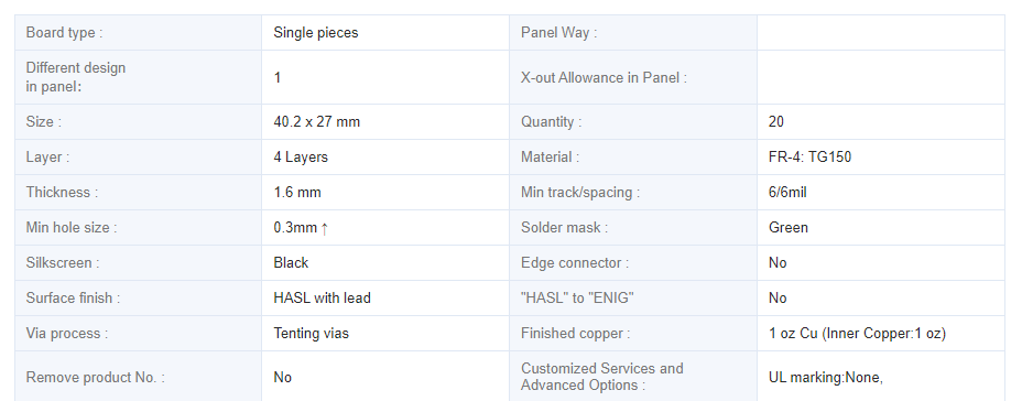
Also here are pics of the PCB’s (I printed 20 of them) 1oz inner and 1oz finish copper


