Over the past two weeks we’ve observed strange flight behavior on our hexacopter flight platform, which we finally tracked down to be related to some kind of motor controller issue.
Auterion Skynode Flight Controller (basically a Pixhawk FMUv5X), running PX4
Myxa ESCs running Telega v1.0, controlled via PWM (yes, I know… )
Myxa’s CAN1 for configuration and monitoring only, shared with FMU and GPS units communicating via DroneCAN
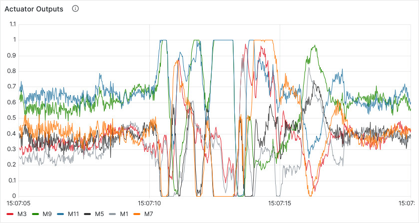
As mentioned above, the Myxas are controlled via PWM, configured to run in velocity-controlled mode (aux.ctl.mode: dv 300.0). After many months of successful operation, the ESC driving motor 5 (UID 32000d00…) started acting weird: occasionally it seems to ignore the setpoint received via PWM, throttling up to maximum power.
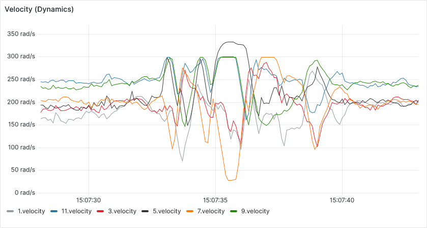
The first picture below shows PX4-sent actuator signals, the second plot shows the velocity reported by Myxa (dynamics port).
With M5, one can see the velocity setpoint and feedback diverging greatly:
Vector control systems actually may have one failure mode where uncontrolled acceleration can occur, but only the voltage control mode is affected and Telega has a mitigation in place that restarts the estimator within a few milliseconds from the onset of the failure before the rotor has a chance to accelerate. This is not what you’re dealing with, I am just providing some background.
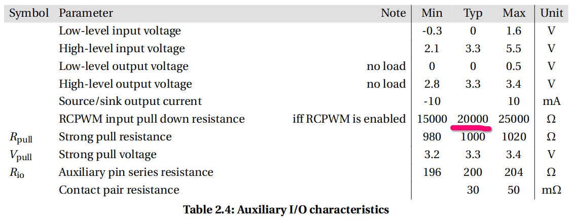
We encountered the described behavior multiple times while bench-testing larger drives in RCPWM control mode. This occurs when the electrical connection of the analog port connector is poor; when the connection is broken, the analog input pin becomes almost floating – it is tied to the ground via a 20 kohm resistor only:
Depending on how the wiring is organized, the EMI from the power stage can be strong enough to cause the pin to flip in a pattern roughly following the phase currents, which is sometimes interpreted by the RCPWM demodulator as a valid signal. It is enough for a false signal to occur once to trigger a positive-feedback runaway process, where the drive accelerates based the first false high-value setpoint, then the acceleration causes stronger EMI at the analog pin and the process thus becomes self-sustaining.
There is an option to enable strong pull via the aux.pull parameter; however, this won’t really address the root of the problem but rather make the drive shut down in a predictable manner instead of accelerating uncontrollably. Also, it requires the RCPWM signal source to have a sufficiently low impedance to override the strong pull resistor, which is not always the case – there have been reports on this forum of Telega-based drives failing to respond to RCPWM signal when the pull resistor is enabled.
 )
)