“Well, look at you, choom—scraping together enough eddies to snag yourself a shiny new FluxGrip! Real slick. Don’t fry it on your first run, yeah?”
This guide will introduce you to the basics of interacting with the FluxGrip, we’ll cover the following:
- How to control the magnet using Cyphal/CAN (Ubuntu)
- How to control the magnet using RC PWM (Arduino + any OS)
- How to control the magnet using Voltage level (Arduino + any OS)
- Different LED patterns and what they mean
- How to update the firmware (Ubuntu)
Note: I’ll be using an Arduino Nano throughout the tutorial, but the same code has also been tested and works with Arduino Nano.
A more rigorous description of the product is available in the reference manual at fluxgrip.zubax.com.
Cyphal/CAN
This is the most sophisticated way to interact with the magnet, it might take a bit more effort but if you’re planning to build cybersystems at a high level, this is the way to go!
Preparation
- Before we get started, make sure you have the following hardware at your disposal:
- Ubuntu computer (any Linux setup will do really)
- CANFace: alllows our computer to interact with CAN networks
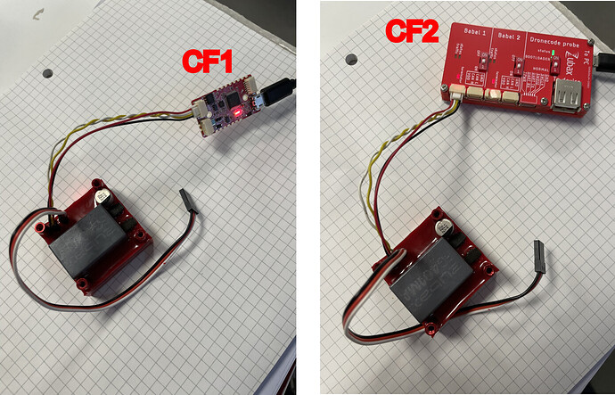
- Connect FluxGrip to CANFace, connect CANFace to computer:
- Before we get started, we need to install some software:
yakut→ Cyphal CLI tool which will be running on our computer
mkdir ~/fluxgrip_demo
cd ~/fluxgrip_demo
python3 -m venv .venv
. .venv/bin/activate # Active virtual environment
pip install yakut
setup_slcan→ Connects CAN interface to SocketCAN
mkdir ~/fluxgrip_demo
cd ~/fluxgrip_demo
wget https://gist.github.com/pavel-kirienko/32e395683e8b7f49e71413aebf5e1a89/raw/f08e426e6c963a5d68868084cd2fab2a469bf76f/setup_slcan
chmod +x ./setup_slcan # Make it executable!
# Optional:
# (script will be accessible from anywhere, not just ~/fluxgrip_demo)
# sudo mv ./setup_slcan /usr/local/bin
# This will set up the SocketCAN interface:
sudo ./setup_slcan --remove-all -r /dev/serial/by-id/usb-*Zubax*Babel*
The SocketCAN interfaces appear as follows:
(If you’re using CF1, you’ll only see one interface)
- Clone all necessary DSDL files (these define the data types that are used on the Cyphal network, DSDL stands for data structure description language, for more information see The Cyphal Guide)
cd ~/fluxgrip_demo
git clone https://github.com/OpenCyphal/public_regulated_data_types/ # Standard Cyphal DSDL types
git clone https://github.com/Zubax/zubax_dsdl/ # Zubax-specific DSDL types
- You’ll need to set up some environment variables for Cyphal/CAN to work
# Create a file called my_env.sh
touch ~/fluxgrip_demo/my_env.sh
my_env.sh contains the following:
. .venv/bin/activate
export CYPHAL_PATH="$HOME/fluxgrip_demo/zubax_dsdl:$HOME/fluxgrip_demo/public_regulated_data_types"
export UAVCAN__CAN__IFACE='socketcan:slcan0' # If you're using CF2 -> 'socketcan:slcan0 socketcan:slcan1'
export UAVCAN__CAN__MTU=8
export UAVCAN__NODE__ID=$(yakut accommodate)

echo "Auto-selected node-ID for this session: $UAVCAN__NODE__ID"
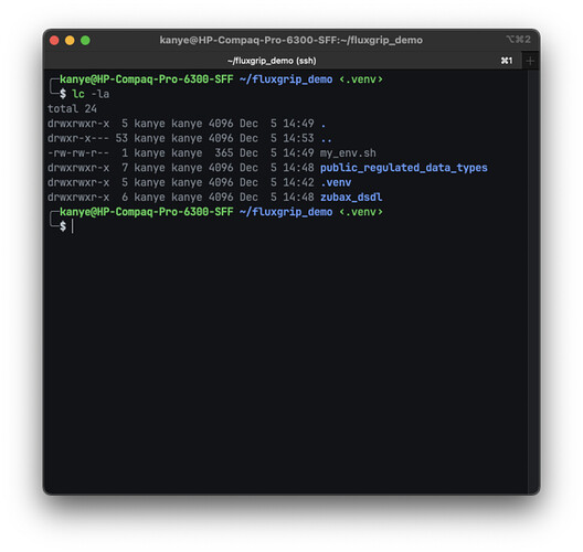
Your folder should now look as follows:
Monitoring
Our first step is to run yakut monitor, this will:
- Launch a Cyphal node on your computer
- Connect to the Cyphal/CAN network
- List all the nodes that are present on said network
To do this, execute the following commands in a terminal window:
cd ~/fluxgrip_demo
source ./my_env.sh
yakut monitor --plug-and-play=pnp.db
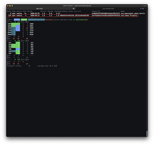
If you’ve done all the previous steps correctly you should see the following:
The first node/row is the monitoring node running on our computer, we are however interested in the second now, which shows the magnet.
Let’s go from left to right and see what is actually shown here:
NodID: stands for “Node ID”, in Cyphal each node is assigned it’s own specific Node ID to facilitate communicationMode: This will tell you whether a device is Operational (oper), updating its software (swup), or not working properly (warn).Health: Tells whether any issues have been detected on the deviceVSSC: Stands for “Vendor Specific Status Code”, this is device-dependent, you’ll find the meaning for this particular number in the FluxGrip datasheet (4 means that it’s operating normally, see section “3.2.1 Heartbeat” in FluxGrip datasheet)Uptime: Self-explanatory, how long the device has been connected to the network, it can be useful indicator to see whether a device has been rebooted (upon reboot Uptime will reset back to zero).VProtcl: Version of OpenCyphal protocal that is runningVHardwr: Hardware version of the deviceVSoftware: Software version running on the deviceUniqueID: Each device is uniquely identified by this number, used for quality tracking.Name: Name of the device
The table below that provides information on the Messages (MESSG) and Services (RQ+RS, request-and-respone) that are present on the network, for now this is not as important, but if you’re interested in learning more, see opencyphal.org.
Observing
Let’s open another terminal window and try to subscribe to the FluxGrip directly and see what kind of information it provides.
cd ~/fluxgrip_demo
source ./my_env.sh
yakut subscribe 1001:zubax.fluxgrip.feedback --redraw
Let’s break down this last command:
subscribe: we want to notify yakut to subscribe to some Message (remember how I said that Cyphal relies on Messages and Services to facilitate its communications?)1001: This is the Message ID which we will be subscribing to, if you look at the monitor window you might note the following:- Node 125 (FluxGrip) publishes (blue background) once per seconds (1 ∑t/s) resulting in usage of 7 bytes per second (7 ∑B/s) on the network to Message ID 1001.
-
zubax.fluxgrip.feedback: This is the DSDL type of the Message, you can actually find exactly what this type consists of by looking forzubax/fluxgrip/feedback.0.1.dsdlat the Zubax/zubax_dsdl repository. -
--redraw: This option will forces a re-renders on the terminal screen (instead of continually printing anew) so it doesn’t pollute your attention.
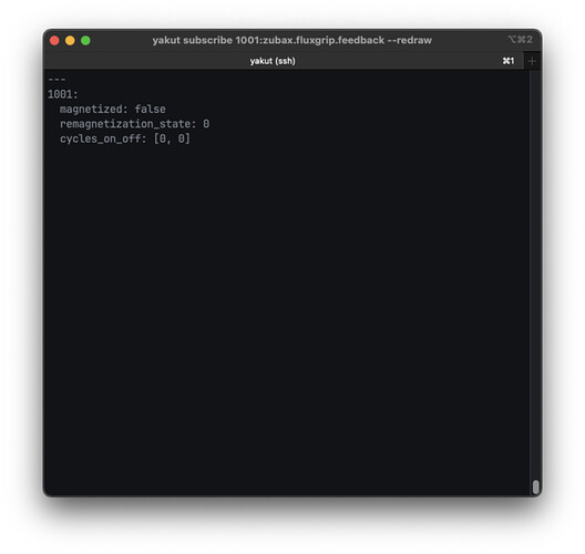
The output from this command looks as follows:
It answers the following basic questions:
- Is it magnetized?
- Is it currently being demagnetized (
-1), idle (0) or magnetized (1)?- You can find out what each option means by reading the comments in the DSDL file!
- How many times has it turned on (first number) or off (second number)?
Controlling
Let’s open a third terminal window which we will use to actually control the magnet.
cd ~/fluxgrip_demo
source ./my_env.sh
yakut publish -N2 1000:uavcan.primitive.scalar.integer8 1
Breaking down this last command:
publish: we want yakut to publish some Message (to control the state of the magnet)-N1: Number of times message is published.1000: This is the Message ID which we will be publish to, if you look at the monitor window, you’ll note the following:- Node 125 (FluxGrip) is subscribed to (green background) to Message ID 1000. (Publishing frequency and data usage are both zero since no node is publishing anything on that Message ID)
uavcan.primitive.scalar.integer8: This is one of the “standard” DSDL types (you can recognize them cause they start withuavcan.), this is a regularuint8_t(see uavcan/primitive/scalar/Integer8.1.0.dsdl in OpenCyphal/public_regulated_data_types repository) which in our case will be used to control the state of the magnet (1turning the magnet on,0turning the magnet off). You can also find this information in the datasheet
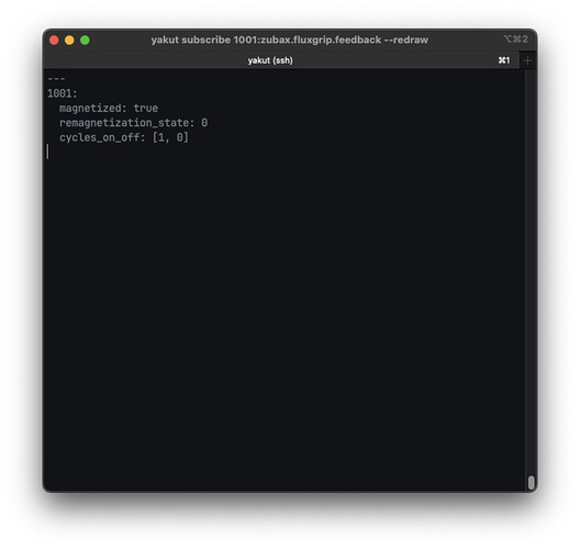
After executing this command you should hear your magnet turning on and it should become magnetized. The terminal window that is subscribed to the Feedback Message from the FluxGrip should also reflect this change in state:
RC PWM
RC PWM is an industry-standard interface that is used literally everywhere – flight controllers, robotic submarines, low-cost robotic arms,…
We require an additional external power supply (5-30V), as the Arduino by itself is unable to provide the necessary power!
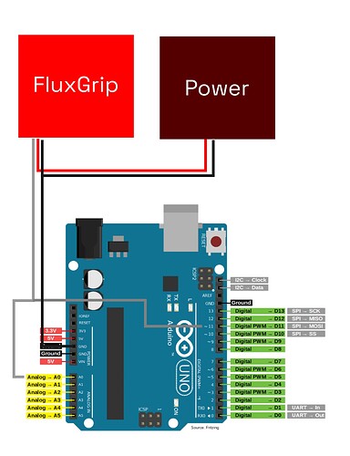
The setup looks as follows (grey/white is the Analog input/control; red and black are, respecitively, power and ground):
The Arduino code looks as follows:
// General
constexpr int BAUD_RATE = 9600;

// Analog Feedback related
constexpr int ANALOG_PIN = A0;
constexpr float REFERENCE_VOLTAGE = 5.0;
unsigned long previousMillis = 0;
constexpr unsigned long FEEDBACK_INTERVAL = 1000;  // 1s

// PWM Control related
constexpr int PWM_PIN = 11;  // D11

namespace analog_feedback {
float read() {
  int analogValue = 0;
  float voltage = 0.0;

  analogValue = analogRead(ANALOG_PIN);
  voltage = (analogValue * REFERENCE_VOLTAGE) / 1023.0;

  return voltage;
}
}  // namespace analog_feedback

namespace pwm_control {
// Frequency PWM = Clock / (Prescaler * 255)
//               = 16,000,000 / (256 * 255) = 245 Hz ~= 250 Hz
// Period = 1/250 = 4 ms
// OFF:   requires between 0.8-1.2 ms -> 25% duty cycle = 1.0 ms
// ON:    requires between 1.6-1.9 ms -> 45% duty cycle = 1.8 ms
// FORCE: requires between 2.1-2.5 ms -> 55% duty cycle = 2.2 ms

namespace command_off {
const uint8_t dutyCyclePct = 25;
}  // namespace command_off
namespace command_on {
const uint8_t dutyCyclePct = 45;
}  // namespace command_on
namespace command_force {
const uint8_t dutyCyclePct = 55;
}  // namespace command_force

void leaveFloating() {
  pinMode(PWM_PIN, INPUT);
}

void setPWM(uint8_t dutyCyclePct) {
  pinMode(PWM_PIN, OUTPUT);

  TCCR2A = _BV(COM2A1) | _BV(COM2B1) | _BV(WGM21) | _BV(WGM20);
  TCCR2B = _BV(CS22) | _BV(CS21); // Clock divided by 256

  OCR2A = 255 * (uint32_t) dutyCyclePct / 100; // 255 is 100% duty cycle
}

void setForce() {
  pinMode(PWM_PIN, OUTPUT);
  setPWM(command_force::dutyCyclePct);
  delay(100); // 100ms
  leaveFloating();
}

void setOn() {
  pinMode(PWM_PIN, OUTPUT);
  setPWM(command_on::dutyCyclePct);
  delay(100); // 100ms
  leaveFloating();
}

void setOff() {
  pinMode(PWM_PIN, OUTPUT);
  setPWM(command_off::dutyCyclePct);
  delay(100); // 100ms
  leaveFloating();
}

}  // namespace pwm_control

void setup() {
  Serial.begin(BAUD_RATE);
  pinMode(ANALOG_PIN, INPUT);
  pwm_control::leaveFloating();
}

void loop() {

  /// ANALOG FEEDBACK ///
  // 1. Read the feedback voltage
  // 2. Print the current state of the magnet
  // 3. Repeat once every second
  unsigned long currentMillis = millis();
  if (currentMillis - previousMillis >= FEEDBACK_INTERVAL) {
    previousMillis = currentMillis;

    float voltage = analog_feedback::read();
    if (voltage >= 1.40 && voltage <= 1.90) {
      Serial.print("Magnet state: UNKNOWN\n");
    }
    else if (voltage < 0.5) {
      Serial.print("Magnet state: OFF\n");
    }
    else if (voltage > 3.0) {
      Serial.print("Magnet state: ON\n");
    }
    else
    {
      Serial.print("Voltage not within any expected range: ");
      Serial.print(voltage);
      Serial.print("V\n");
    }
  }

  /// PWM CONTROL ///
  if (Serial.available() > 0)
  {
    const char received = Serial.read();

    if (received == 'M') // Magnetize
    {
      Serial.print("Setting PWM to ON\n");
      pwm_control::setOn();
    }
    else if (received == 'D') // Demagnetize
    {
      Serial.print("Setting PWM to OFF\n");
      pwm_control::setOff();
    }
    else if (received == 'F') // Force
    {
      Serial.print("Setting PWM to FORCE\n");
      pwm_control::setForce();
    }

  }
}
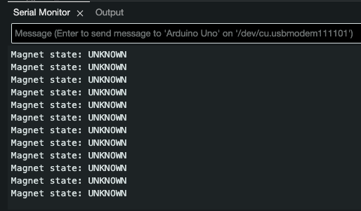
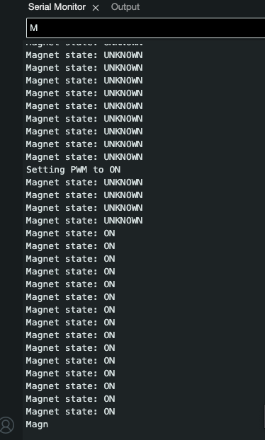
When you turn on FluxGrip for the first time it will be in Detect state, which means that the current state of the magnet is yet unknown, this will be printed in the Serial ouput window:
Using the Serial monitor you can send three different commands:
- ON: by sending
M - OFF: by sending
D - FORCE: by sending
F(this will turn on the magnet regardless of current state)
For example, sending M results in the following:
Voltage level
We require an additional external power supply (5-30V), as the Arduino by itself is unable to provide the necessary power!
The setup is exactly the same as for RC PWM (see section above).
The Arduino code looks as follows:
// General
constexpr int BAUD_RATE = 9600;

// Analog Feedback related
constexpr int ANALOG_PIN = A0;
constexpr float REFERENCE_VOLTAGE = 5.0;
unsigned long previousMillis = 0;
constexpr unsigned long FEEDBACK_INTERVAL = 1000;  // 1s

// Voltage Control related
constexpr int VOLTAGE_PIN = 11; // D11

namespace analog_feedback {
float read() {
  int analogValue = 0;
  float voltage = 0.0;

  analogValue = analogRead(ANALOG_PIN);
  voltage = (analogValue * REFERENCE_VOLTAGE) / 1023.0;

  return voltage;
}
}  // namespace analog_feedback

namespace voltage_control {

void setOn() {
  pinMode(VOLTAGE_PIN, OUTPUT);
  digitalWrite(VOLTAGE_PIN, HIGH);
}

void setOff() {
  pinMode(VOLTAGE_PIN, OUTPUT);
  digitalWrite(VOLTAGE_PIN, LOW);
}

void setForce() {
  pinMode(VOLTAGE_PIN, OUTPUT);
  digitalWrite(VOLTAGE_PIN, HIGH);
}

}  // namespace pwm_control

void setup() {
  Serial.begin(BAUD_RATE);
  pinMode(ANALOG_PIN, INPUT);
  pinMode(VOLTAGE_PIN, INPUT); // Leave floating
}

void loop() {

  /// ANALOG FEEDBACK ///
  // 1. Read the feedback voltage
  // 2. Print the current state of the magnet
  // 3. Repeat once every second
  unsigned long currentMillis = millis();
  if (currentMillis - previousMillis >= FEEDBACK_INTERVAL) {
    previousMillis = currentMillis;

    float voltage = analog_feedback::read();
    if (voltage >= 1.40 && voltage <= 1.90) {
      Serial.print("Magnet state: UNKNOWN\n");
    }
    else if (voltage < 0.5) {
      Serial.print("Magnet state: OFF\n");
    }
    else if (voltage > 3.0) {
      Serial.print("Magnet state: ON\n");
    }
    else
    {
      Serial.print("Voltage not within any expected range: ");
      Serial.print(voltage);
      Serial.print("V\n");
    }
  }

  /// VOLTAGE CONTROL ///
  if (Serial.available() > 0)
  {
    const char received = Serial.read();

    if (received == 'M') // Magnetize
    {
      Serial.print("Setting Voltage to ON\n");
      voltage_control::setOn();
    }
    else if (received == 'D') // Demagnetize
    {
      Serial.print("Setting Voltage to OFF\n");
      voltage_control::setOff();
    }
    else if (received == 'F') // Force
    {
      Serial.print("Setting Voltage to FORCE\n");
      voltage_control::setForce();
    }
  }
}
Note: the ON command requires a voltage between 2.5V and 3.8V, however Arduino does not have any DAC, so we’re just relying on 5V (which is a FORCE command) instead.
LED patterns
Magnet-related
- Magnet is in Detect state (Unknown): the default state upon turning on
- Magnet is ON
- Magnet is OFF
- Magnet is “Turning On”
- Magnet is “Turning Off”
CAN-related
- CAN is down
- CAN is up
Firmware update
To update the firmware, we will once more rely on Cyphal/CAN, if you haven’t done the setup as outlined in the first section, please do so now.
Download the latest firmware from files.zubax.com and put it in ~/fluxgrip_demo (same folder that we created in the first section).
We’ll need 2 windows:
- one window for monitoring the node as it goes into “software update” mode (
swup):
cd ~/fluxgrip_demo
. .venv/bin/activate
sudo setup_slcan --remove-all -r /dev/serial/by-id/usb-*Zubax*Babel*
source ./my_env.sh
yakut monitor --plug-and-play=pnp.db
- one window that will function as the “file-server”, sending the new firmware binary to the FluxGrip:
cd ~/fluxgrip_demo
. .venv/bin/activate
source ./my_env.sh
yakut --verbose file-server --update-software
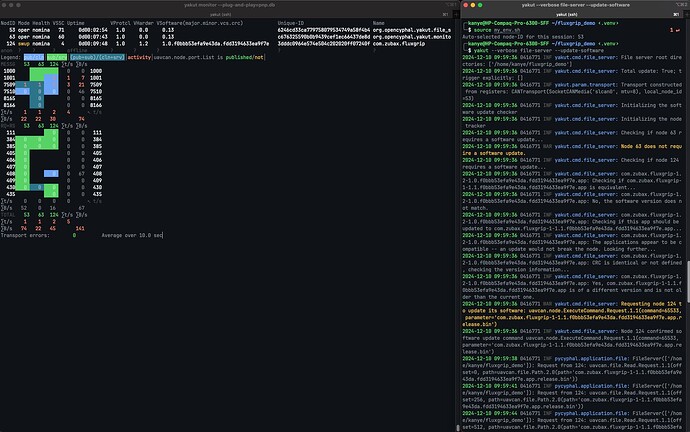
If you’ve done everything successfully it should look as follows:
Note: I have changed the version of the firmware from 1.0 to 1.1, in order to trigger a firmware update, however this is the same binary (same VCS), so this is just an example to illustrate how it works. In your case you will only need to update the firmware when there is actually a new firmware version (and then major/minor will be increased).
Note 2: Loading a new firmware binary takes around 50 minutes.
If you have any questions, feel free to post them below!

