T-Motor Alpha 60A 12S was tested side-by-side with Zubax Myxa A0 to compare their energy efficiency and response linearity. This post summarizes the results.
The test was arranged as follows: motor T-Motor MN501-S 240KV with foldable propeller T-Motor 22.2x7.2 installed on the RCbenchmark 1580 dynamometer. One ESC connected to the motor and commanded via RCPWM with the setpoint swept from 1100 us to 2000 us and back over one minute. Data was collected using the RCBenchmark CSV export feature. After the test, the motor was left to cool for one hour, then the other ESC was installed, and the test was repeated. The ambient air temperature and pressure were constant. The exported results have been visualized using a custom visualization script.
Visualization script
Script: dynamometer_visualizer.py (10.7 KB)
Requirements:
pandas      ~= 2.0
numpy       ~= 1.24
plotly      ~= 5.15
click       ~= 8.1
During the test, the electrical power was supplied from a 1.5 kW lab power supply set to 25 V with a 0.1 F braking capacitor attached. This setup emulates a nearly fully charged 6S \text{Li} \text{Co} \text{O}_2 battery.
The parameters of the motor and the propeller have been measured and added to the following public spreadsheets:
Per the requirements of the end application this setup is intended for (a multirotor unmanned vehicle), the operating conditions of interest are the following:
| Mode | Angular velocity [radian/second] | Torque [newton*meter] | Thrust [newton] |
|---|---|---|---|
| Nominal | 300 | 0.6 | 19 |
| Peak | 410 | 0.9 | 35 |
Given the above requirements and the motor parameters, the key figures at the two operating points amount to the following (nominal and peak):
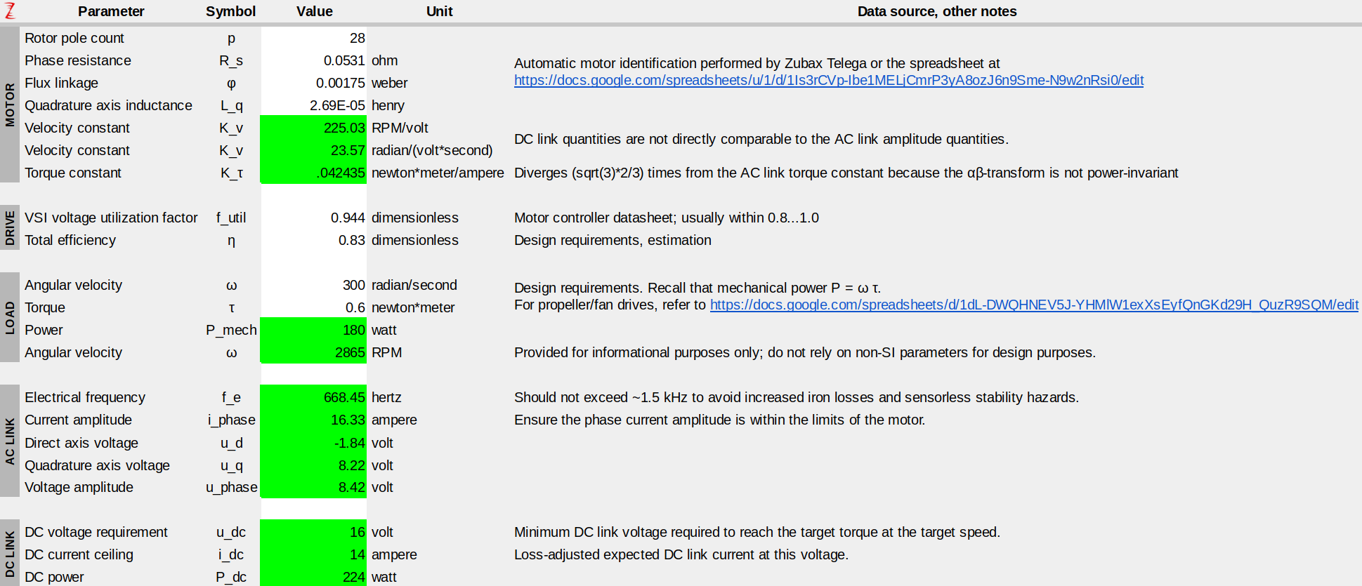

The screenshots are taken from our publicly available helper spreadsheet. For the related theory, please refer to Motor control fundamentals - Telega v1.0 Reference Manual.
A reader familiar with the subject matter will point out that the chosen setup is suboptimal. The problem is that the static torque constant C_q = 3.02 \times 10^{-3} of this propeller is too high for the chosen operating point and the maximum current of the motor. This creates a high load torque that forces the motor to operate at a low electrical frequency (ca. 700 Hz around the nominal operating point) and comparatively low voltage, resulting in high phase current and high resistive losses. This deficiency is easy to correct by choosing a different motor with either a greater number of poles or a stronger flux linkage (i.e., lower K_v, which takes either stronger magnets or an increased number of winding turns) — either measure will increase the voltage and proportionally reduce the current.
Further, both ESCs support a DC link voltage of up to 12 S; increasing the voltage allows for the reduction of ohmic losses in the DC link, even if the rest of the powertrain remains unchanged.
Designing the powertrain such that the peak velocity matches the minimum battery voltage is a common approach. Its disadvantage is that the available DC voltage remains heavily underutilized around the nominal operating point, meaning that there is some potential for optimization. This can be addressed by enabling the flux weakening mode (which is supported by all Telega-based drives, such as Myxa, unlike most competing products) such that the drive operates at the maximum voltage in the nominal region and resorts to the flux weakening only during the brief peak load condition. Interested readers may learn more at Motor control fundamentals - Telega v1.0 Reference Manual.
Unfortunately, suboptimal powertrain design is a common problem pervasive throughout the industry. This results in wasted energy, reduced endurance, and increased operating and maintenance costs. We advise customers who are seeking to maximize the economic efficiency of their products to consult with a subject matter expert — such as Zubax Robotics — before committing to a specific design. Please reach out to us via sales@zubax.com.
Despite the suboptimal drivetrain design, the setup allows us to perform a fair side-by-side comparison of the two ESCs, as the conditions are identical. The results are shown below.
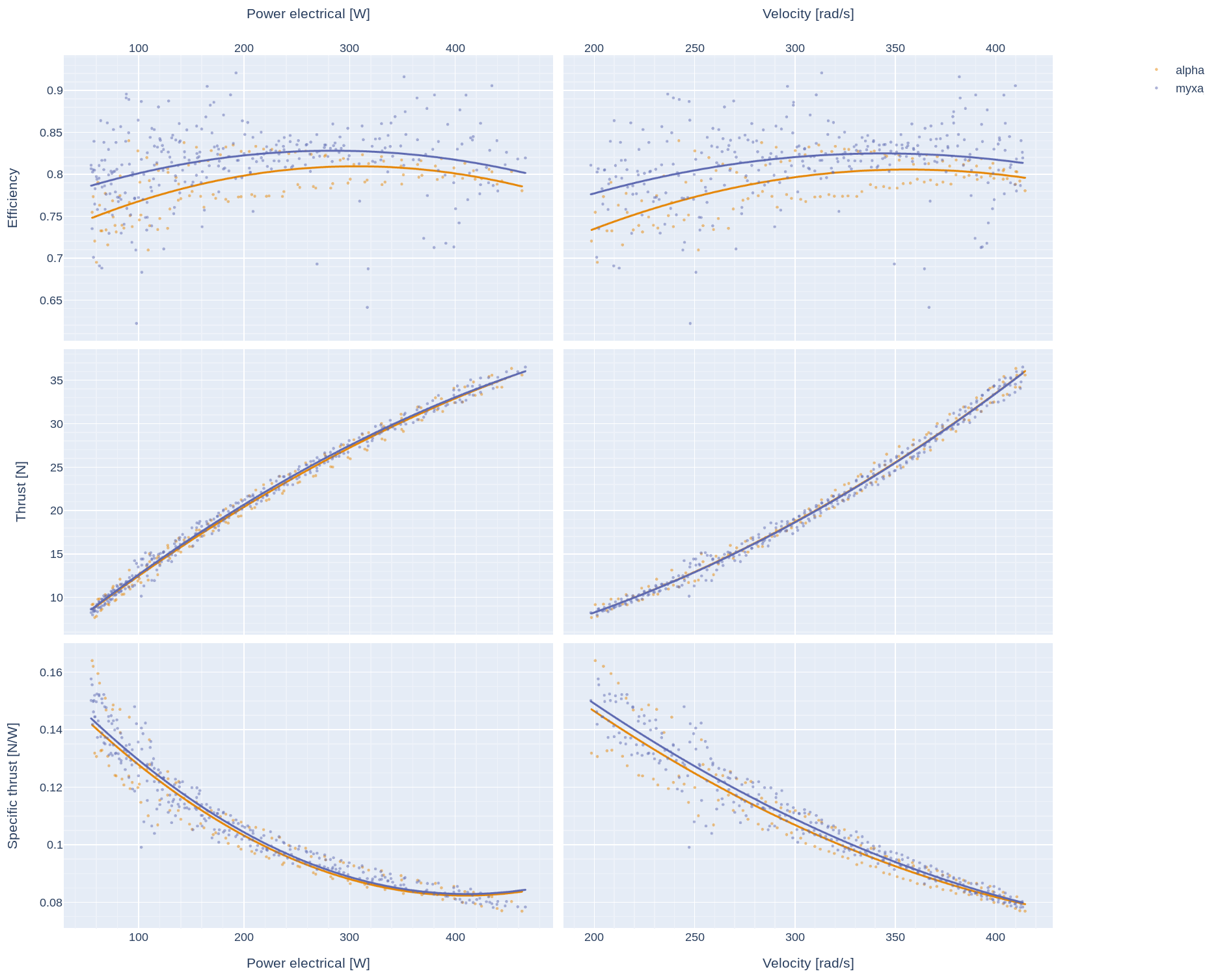
The higher efficiency of Myxa is critical not only in energy saving but also in mass reduction. This is because the reduced heat dissipation — achieved through the superior motor control technology that is among the best available today — eliminates the need for massive heatsinks and bulky enclosures thereby reducing the mass of the airframe and saving valuable space onboard. As such, Myxa is almost 2x lighter than the competitor, more energy-efficient, and does not require a heat sink to deliver the required power output.
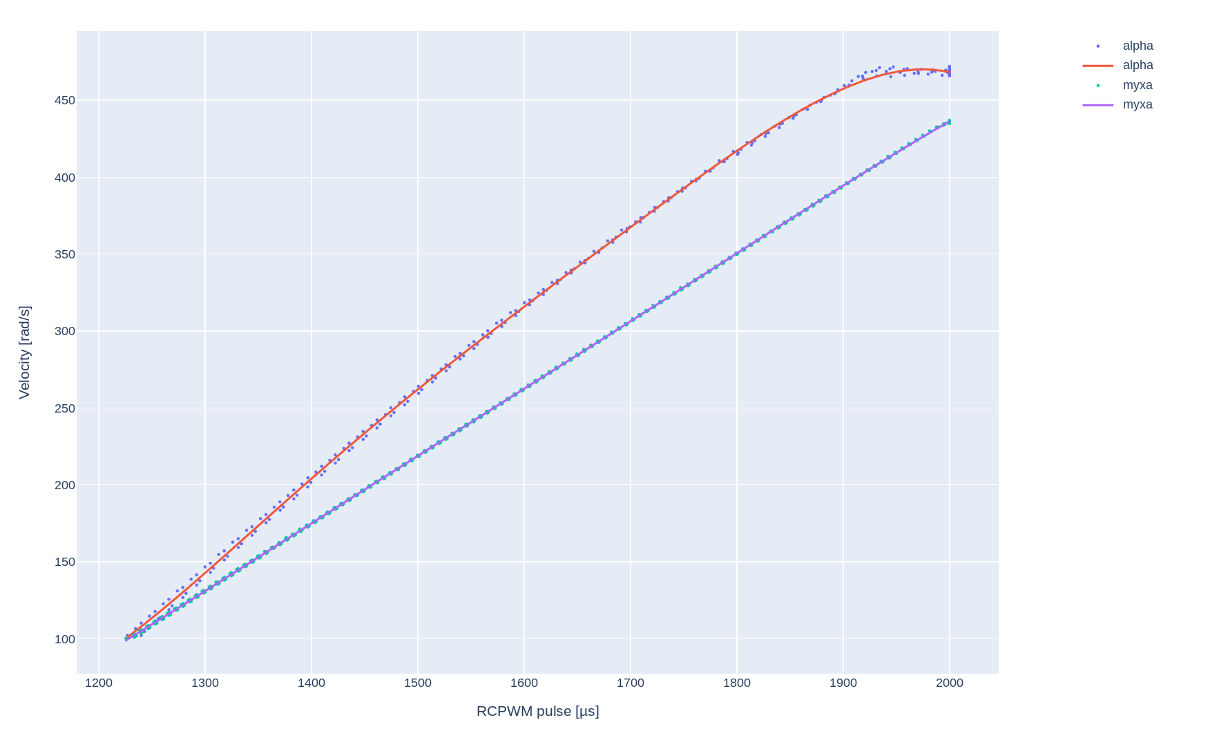
Since this drive is intended for a multirotor vehicle, the time constant of the velocity response is critical. To meet this requirement, Myxa has been configured to operate in the INDI velocity control mode (INDI stands for “incremental nonlinear dynamics inversion,” an advanced adaptive velocity controller; learn more from the Telega Reference Manual). INDI provides a fast and stable response that outperforms competing technologies (such as feed-forward PID or fuzzy controllers); this is especially critical for multirotor vehicles. This mode provides a very linear velocity response irrespective of the battery voltage and propeller velocity, enabling highly robust attitude control:
The Myxa was configured as follows during this test:
# RCPWM interface configuration
aux.ctl.1_rcpwm.deadband:       80.0e-6
aux.ctl.1_rcpwm.rev_mid_fwd:    [1.0e-3, 1.0e-3, 2.0e-3]
aux.ctl.mode:                   dv 440  # Use velocity control mode with the limit of 440 rad/s
aux.ctl.type:                   1

# Spinup configuration
drive.runner.0_ramp.spinup_current_pu:      [0.3, 0.3]
drive.runner.0_ramp.spinup_duration:        [0.2, 0.0, 1.0, 0.002, 0.015, 0.6]
drive.runner.0_ramp.velocity_stall_spinup:  [30.0, 50.0]
drive.runner.type: 0

# Velocity controller configuration
drive.velocity_ctl.2_indi.acceleration_pi:  [50, 0]
drive.velocity_ctl.2_indi.mass:             0.00004  # Set to 0.00005 for a more aggressive response.
drive.velocity_ctl.acceleration:            [-10000.0, 10000.0]
drive.velocity_ctl.type:                    2

# Motor model
motor.current_ctl_bwr:  0.05
motor.current_max:      45  # The actual motor limit is 25A; we set a higher limit to enable faster velocity response.
motor.current_ramp:     5000.0
motor.resistance:       0.0530613214
motor.inductance_dq:    [26.8788e-6, 26.8788e-6]
motor.flux_linkage:     0.001749722
motor.mechanical_ratio: 14  # 28 poles
Zubax Robotics offers top-tier motor control solutions for the most demanding applications. Please explore our offers at https://zubax.com and reach out to sales@zubax.com for a consultation.