Reliable and efficient operation of a sensorless drive is critically dependent on the correct modeling of the motor by the drive controller. In many practical scenarios, especially those that involve low-cost, low-power motors, the parameters of the motor are often either known with a large degree of uncertainty or are not known at all, depending on the diligence of the motor’s manufacturer. In such scenarios, automatic motor parameter measurement (aka motor identification) that can be performed by Telega-based drives is invaluable.
For a typical PMSM vector control application the three most critical motor parameters are its phase resistance R_s, direct/quadrature inductance L_{dq}=\left\{L_d,L_q\right\}, and the magnetic flux linkage \phi. While critical, the resistance and the flux linkage are relatively trivial to measure automatically, so from the standpoint of drive tuning, they pose little interest, while the inductance can get a bit convoluted.
In Telega, the motor inductance is used in two key components: the motor state estimator and the phase current controllers. The state estimator models the motor using some variation of the standard PMSM model, here it is expressed in the DQ frame (rotating frame):
where u – voltage, i – current, \omega – angular velocity in electrical radian/second.
The thing to note in the equations is that the influence of the inductance on the behavior of the motor is proportional to the current or its time gradient. Hence, the first piece of evidence that your inductance settings are incorrect is that the drive is stable under low load but exhibits issues (such as stalling or high reactive power) under high load, i.e., \left|I_q\right| \gg 0, or when the load is changed abruptly.
NB: The current setpoint ramp can be used to manage load gradients; the corresponding configuration parameter is m.current_ramp.
The second component where the inductance is critical is the phase current controller. By default, ignoring certain details and special requirements, the i_{dq} current vector is often controlled by a simple sequential PI controller. The gain of the controller, per axis, can be approximated as:
Where b – bandwidth ratio (BWR) is the ratio of the i_{dq} controller bandwidth to its update frequency (which equals the motor control tick freqency, which often equals the PWM frequency) [dimensionless]. The R and L are the resistance and inductance of the corresponding axis (d or q).
The default value of b is often around 0.06, depending on the firmware revision and the type of AC modulator used. Higher values increase the responsiveness of the drive to load and speed variation but also increase the risk of self-induced oscillation along with the phase noise level. Lower values produce smoother phase voltage and reduced noise but increase the risk of stalling the motor in the face of rapid transients. For most practical applications b \in (0.01, 0.2).
A self-induced oscillation in the phase current control loop makes the motor produce high-pitched whining noise even at zero load and/or at a standstill. If this effect is observed even at approx. b < 0.05, this might indicate that the inductance values that were used to compute the gains of the current controller are incorrect. Another piece of evidence is when the reduction of b resolves the self-oscillation problem but at the same time causes the motor to stall under load and/or during rapid load variation, while under ~zero load the motor is able to reach high velocity without significant issues (refer to the state equations above).
NB: One simple empirical way of testing whether the phase current control loop is tuned properly is to configure Telega to drive the motor in the passive spinup mode (or any other mode that allows the drive to be operating at standstill and zero torque) with a zero torque setpoint and then rotate the motor by hand forward/backward, quickly alternating the direction of rotation. If the loop is tuned properly, you should not experience any noticeable resistance to the motion and the motor should not be making any significant audible noise. If there is resistance, the current control loop is over-damped, and the BWR should be increased. If the motor makes a high-pitched whining noise, the loop is self-oscillating, so the BWR should be reduced.
Suppose that, based on the above, there is a reasonable suspicion that the inductance is measured incorrectly. In practice, if the inductance is measured incorrectly, then it is likely to be greater than the actual value. In the absence of adequate measurement tools, one might address this problem by systematically reducing the configured inductance (parameter m.inductance_dq) until the stable operation is achieved, assuming that L_d \approx L_q.
A more efficient approach, however, is to use an LCR meter to measure the inductance directly. Remember that for most PMSM, L_d < L_q. In order to avoid the hassle of keeping the rotor aligned along the direct and quadrature axis separately during the measurement process, it is recommended to rotate the rotor very slowly during the inductance measurement process and record the lowest and the highest measurements, which are the direct and the quadrature inductance, respectively. The recommended excitation parameters for the measurement are approx. 1 kHz at 1 V.
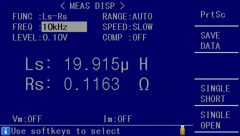
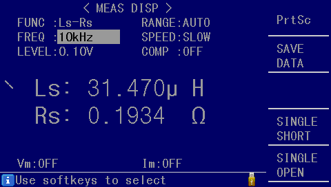
Here’s an example for a VTOL drone motor, direct and quadrature, respectively:


These are phase-to-phase inductances while Telega expects phase inductance values; therefore, divide the measured values by two and enter the result as m.inductance_dq; in this example, that would be L_d = 10 \mu{}H, L_q = 15 \mu{}H. The automatically identified inductance value for this particular motor was L_d = L_q = 13 \mu{}H, which is reasonably close (Telega is currently unable to measure direct and quadrature inductances separately).
There is at least one precedent where the automatically measured inductance of a hub motor for an e-scooter was 582 \mu{}H while the LCR meter produced a very different but more correct estimate of \approx 100 \mu{}H.